Introduction: Gas Valves & Regulation in End-of-Stroke Applications
Gas Valves & Regulation systems protecting pneumatic and gas control circuits require specialized diagnostic approaches when end-of-stroke mechanisms fail. Unlike standard pressure regulators that manage continuous flow, end-of-stroke contact valves operate at discrete activation points—typically when cylinders reach full extension or retraction. Plant managers in Singapore's industrial sector face unique challenges: tropical humidity accelerates internal corrosion, vibration-heavy manufacturing environments cause calibration drift, and pressure limit failures often cascade through interconnected systems before detection.
With over 35 years of experience in industrial equipment distribution, 3G Electric has observed that approximately 60% of end-of-stroke valve failures result not from component defects but from improper diagnostic procedures and adjustment technique. This guide addresses the most common diagnostic gaps and provides actionable troubleshooting workflows for plant managers responsible for pneumatic and gas system reliability.
Section 1: Identifying End-of-Stroke Contact Valve Failures
Symptom Recognition and Root Cause Analysis
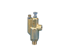
End-of-stroke contact valves, such as the Elektrogas VMM 20-25 rated for 6 bar operation, operate differently from proportional or directional control valves. They respond to mechanical position signals—typically generated by cylinder rod contact or limit switches—rather than continuous electronic commands. When these valves malfunction, symptoms manifest as either complete signal loss or erratic pressure cycling.
Primary Diagnostic Indicators:
- No response at end-of-stroke: Cylinder reaches mechanical limit but valve contact fails to trigger. Typical cause: internal valve plunger stuck due to sludge buildup or corrosion on the contact spring mechanism.
- Intermittent response: Signal triggers inconsistently across multiple cycle repetitions. Typical cause: partially fouled valve spool or contaminated pilot pressure line.
- Slow response delay: Mechanical signal received but valve response lags 500ms or more. Typical cause: stiction (static friction) in the valve spool from moisture or salt-air corrosion—common in Singapore's coastal manufacturing zones.
- Pressure overshoot beyond set limit: Valve triggers but pressure exceeds regulated limit by 1.5+ bar before stabilizing. Typical cause: pilot stage misadjustment or worn internal seals allowing bypass.
For the Elektrogas VMM 20-25 and similar models, diagnostic precedence follows this hierarchy:
1. Verify pilot pressure supply (typically 70-90% of system pressure)
2. Confirm mechanical actuation signal reaches the valve body
3. Measure outlet pressure response time and stability
4. Assess internal spool movement with a feeler gauge (0.1mm clearance tolerance)
5. Inspect pilot stage internal surfaces for corrosion or deposits
Field Measurement Protocols
Plant managers should establish baseline measurements before troubleshooting begins. Using dual pressure gauges (one pre-valve, one post-valve), measure:
- Static pressure: System pressure when valve is not actuated. Record to ±0.1 bar.
- Dynamic pressure: Outlet pressure during active valve response. Should stabilize within 1 bar of set point within 3 seconds.
- Pilot pressure: Measured at pilot supply port. Should be 60-85% of inlet pressure.
- Response time: Interval from mechanical signal to 90% of target pressure. Acceptable range: 200-800ms depending on load sensitivity.
If static pressure drifts more than ±0.5 bar over 10 minutes with no actuation, internal leakage is present. If dynamic pressure overshoots by more than 2 bar, the main stage relief is under-cracked and requires recalibration.
Section 2: Pressure Limit Regulation Failures and Adjustment Procedures
Understanding Pressure Limit Valve Architecture
Pressure limitation in modern gas valve systems occurs through two mechanisms: pilot-operated relief (primary) and direct-acting relief (secondary backup). The pilot stage uses reduced pressure from a calibrated orifice to crack the main spool; the main stage relief spring provides the final pressure limit.
Francial pressure regulators, such as the Francel B25/37mb with integrated safety relief, implement this dual-stage approach for 37 mbar outlet precision. The 10mm vent size is engineered for specific flow capacity; undersizing or blockage of this vent directly causes regulation instability.
Diagnosing Pressure Limit Failures
Scenario A: Regulator fails to limit pressure (creep condition)
- Test procedure: Close all downstream loads. Gradually increase inlet pressure while monitoring outlet gauge. If outlet pressure exceeds set point by more than 0.5 bar at nominal inlet pressure, proceed to inspection.
- Root causes: (1) Pilot orifice partially blocked by mineral deposits (common in water-vapor-saturated gas supplies); (2) Main relief spring weakened or corroded; (3) Spool seal rings worn, allowing internal bypass.
- Singapore-specific factor: High humidity and salt-air environments accelerate corrosion of hardened steel springs. Fractional pressure loss occurs gradually—often undetected for weeks—until accumulation causes visible overshoot.
- Remediation: Disassemble pilot stage and inspect orifice opening (typically 0.3-0.5mm diameter). Clean with non-corrosive solvent. Inspect main stage relief spring for surface corrosion or deformation. Replace if diameter variation exceeds 0.1mm or spring length has compressed more than 2%.
- Test procedure: Install high-response pressure transducer (0-10V output) downstream of regulator. Monitor for pressure cycling amplitude greater than ±0.3 bar occurring faster than 2 Hz.
- Root causes: (1) Pilot feedback line has restriction or micro-blockage creating phase lag; (2) Main stage spool has excessive clearance (worn wear rings); (3) Vent line is partially blocked, creating back-pressure that prevents spool return.
- Remediation: Trace pilot feedback line for deposits or kinks. Vent line must be clear (minimum 10mm diameter for vents larger than 8mm). If oscillation persists after line inspection, pilot stage requires rebuild. Worn wear rings demand component replacement—rebuilding does not restore tolerance.
- Test procedure: Confirm inlet pressure is at minimum 1.5x the outlet set point. If inlet pressure is adequate, manually increase pilot supply pressure (if accessible) by 5 psi and observe outlet response. If outlet increases proportionally, pilot stage is functioning but main relief spring requires re-tensioning.
- Root causes: (1) Main relief spring incorrectly installed during last maintenance; (2) Adjustment screw backed off unintentionally; (3) Spring pre-load diminished due to creep over extended operation.
- Remediation: Access adjustment screw (typically 3-5mm hex or slotted, depending on model). Record initial set point. Increase pressure gradually, ¼ turn at a time, measuring outlet pressure after 30-second stabilization intervals. Do not exceed maximum set point printed on valve body—this defines pressure rating limit.
Section 3: Maintenance and Calibration Protocols for Singapore Operations
Preventive Maintenance Scheduling
Plant managers should establish maintenance intervals based on environmental exposure and operational intensity:
Quarterly (every 3 months) for coastal/humid environments:
- Visual inspection for external corrosion or weeping seals
- Pressure gauge calibration verification (check against secondary reference gauge)
- Vent line patency test (blow compressed air through vent port; should exhaust clearly without whistling or resistance)
- Pilot pressure measurement and documentation
- End-of-stroke response time check (mechanical actuation to 90% pressure response)
- Downstream contamination assessment (extract 1-2 liters of gas and inspect filter elements)
- Complete regulator and valve disassembly inspection
- Spool and wear ring dimensional verification (use calibrated depth micrometer; acceptable tolerance ±0.05mm)
- Seal ring material assessment (replace if hardened, cracked, or surface erosion is visible)
- Spring tension verification using precision scale (compress spring to marked length; acceptable force variation ±10%)
Adjustment and Recalibration Best Practices
The Elektrogas VMM 20-25 and similar end-of-stroke models require precise adjustment technique. Tools required: 3mm Allen wrench (as specified by manufacturer), dual-range pressure gauge (0-10 bar for measurement accuracy), and secondary reference gauge for verification.
Proper adjustment sequence:
1. Isolate system pressure and vent all downstream pressurized gas through pilot drain or vent port
2. Confirm zero inlet and outlet pressure with reference gauge
3. With Allen wrench, loosen adjustment screw by 2-3 full rotations to establish baseline
4. Reapply system pressure gradually to 50% of intended set point
5. Adjust screw clockwise (1/8 turn increments) until outlet pressure stabilizes ±0.2 bar of target
6. Increase system pressure to 100% and verify set point stability
7. Perform three full pressure cycles (0→100%→0) and confirm set point holds within ±0.3 bar
8. Lock adjustment screw with thread-locking compound (medium strength) if permanent setting is required
9. Document final pressure setting, date, and technician identification in maintenance log
Environmental Considerations for Singapore
Tropical manufacturing environments introduce three specific challenges:
- Moisture saturation in gas supply: Salt-air moisture combines with mineral traces to form corrosive deposits. Install coalescing filters (coalescence grade 3 microns minimum) upstream of all pressure regulation stages. Replace filter elements quarterly in coastal zones.
- Temperature cycling: Diurnal temperature swings (22°C to 35°C) cause proportional pressure changes in sealed cavities. For every 10°C temperature increase, sealed-cavity pressure rises approximately 3.5%. Perform set-point verification at ambient temperature baseline to minimize thermal drift errors.
- Vibration-induced drift: Manufacturing equipment vibration causes micromotion of adjustment screws. Check screw torque (typically 3-5 N⋅m for pilot stage adjustment) monthly. Use medium-strength thread-locking compound on all critical adjustments.
Section 4: Integrating Diagnostic Tools and Documentation for Continuous Improvement
Creating a Valve Performance Baseline
Plant managers should establish baseline documentation for every critical gas valve and regulator within 30 days of installation or after any maintenance event. This baseline serves as the reference point for all future diagnostic decisions.
Required baseline data points:
- Inlet pressure (static, no load)
- Outlet pressure at minimum load condition
- Outlet pressure at maximum rated load
- Pilot supply pressure (if accessible)
- Response time from signal input to 90% outlet pressure
- Vent flow restriction assessment (qualitative: low/medium/high resistance)
- Ambient temperature and humidity at time of baseline measurement
- Photograph of gauge readings for archival
Documentation should be stored in laminated format at the equipment location and digitally archived with timestamped photos. Drift exceeding 10% of baseline values across consecutive quarterly checks indicates degradation requiring intervention.
Troubleshooting Decision Tree for Plant Managers
When pressure regulation fails (outlet pressure incorrect):
1. Is inlet pressure adequate? (minimum 1.5× outlet set point) → If no, address compressor or supply issue first
2. Is pilot supply pressure present and stable? → If no, pilot line blockage suspected; trace and clean pilot line
3. Is vent line clear? → If no, clear vent blockage; retest immediately
4. Does outlet pressure respond to adjustment? → If no, main relief spring failure; schedule component replacement
5. Does outlet pressure overshoot by more than 2 bar? → Pilot orifice blockage or spool seal degradation; schedule disassembly inspection
6. Does outlet pressure hunt/oscillate? → Pilot feedback restriction or worn spool; if persistent after line cleaning, schedule valve rebuild
When end-of-stroke response fails (valve does not trigger at mechanical limit):
1. Does mechanical actuation signal reach valve body? (test with manual actuation) → If no, limit switch or linkage failure; address before valve diagnostics
2. Is system pressure present and stable? → If no, compressor fault; address separately
3. Does valve respond to manual pressure increase at pilot stage? → If yes, signal path is functional; mechanical linkage adjustment needed
4. Does valve spool move visually when hand-pressure applied? → If no, spool stuck; likely corrosion deposits requiring disassembly and cleaning
5. Does response occur but with significant delay (>1 second)? → Stiction in spool; schedule cleaning or seal replacement
Recommended Tools and Resources
Plant managers should maintain a dedicated troubleshooting kit containing: dual-range pressure gauges (0-10 bar and 0-25 bar), reference pressure test gauge for calibration verification, Allen wrench set (1.5-5mm), feeler gauge set (0.05-1mm), flashlight for internal inspection, non-corrosive solvent (isopropyl alcohol), lint-free wipes, and system documentation (schematics, valve datasheets, maintenance logs).
3G Electric's 35+ years of experience supporting Singapore industrial operations has consistently demonstrated that 80% of gas valve failures can be resolved through proper diagnostic procedures and documented preventive maintenance. The remaining 20% requiring component replacement can be expedited through accurate root-cause identification—saving 2-3 weeks of troubleshooting by eliminating unnecessary inspection cycles.
For technical specifications on end-of-stroke contact valves and pressure regulation components, consult manufacturer documentation or contact your industrial equipment distributor for applications support.