Gas Burner Troubleshooting Guide: Diagnosing Common Issues in Industrial Combustion Systems
Gas burner systems are critical components in industrial heating, sterilisation, and combustion applications across Singapore's manufacturing sector. When these systems malfunction, production downtime and energy inefficiency quickly escalate operational costs. This troubleshooting guide equips maintenance professionals with data-driven diagnostic methods to identify and resolve common burner issues. Whether you're operating compact low-capacity units or high-power industrial installations, understanding the systematic approach to problem diagnosis will minimise equipment downtime and optimise combustion efficiency. We'll explore fault identification across ignition circuits, flame detection systems, gas supply chains, and electronic controls.
Understanding Gas Burner Fault Categories and Diagnostic Framework
Industrial gas burners operate through integrated systems comprising fuel delivery, ignition mechanisms, flame detection, and electronic controls. Faults typically cluster into four primary categories: ignition failures, flame stability issues, fuel delivery problems, and control circuit malfunctions. Each category presents distinct diagnostic signatures that experienced technicians can recognise through systematic observation and measurement.
Ignition failures represent approximately 40% of gas burner service calls. These occur when the ignition circuit fails to establish flame within the specified lockout period—typically 3-5 seconds depending on burner model specifications. Common causes include electrode degradation, inadequate spark gap spacing (typically 2-4mm for industrial systems), fuel pressure below minimum threshold, and control relay malfunction. Modern burners like the FBR gas burners incorporate electronic controls that automatically lockout systems after failed ignition attempts, protecting equipment from hazardous conditions.
Flame stability problems manifest as burner cycling, flame lift-off, or complete extinction during normal operation. These indicate imbalances in the combustion triangle: fuel, air, and ignition. Root causes include blocked air intake passages, nozzle obstruction, incorrect air damper settings, or gas pressure fluctuation. Gas supply issues—whether from regulator malfunction, filter blockage, or inadequate pipe sizing—create pressure variations that destabilise flame characteristics.
Electronic control failures often involve flame detection circuits utilising ionisation electrodes or ultraviolet (UV) cells. These sensors require clean electrode surfaces and correct positioning. Contaminated sensors generate false flame detection signals, causing unnecessary cycling or complete burner shutdown. Control relays, such as the CBM Relay TMG 740-3, serve as critical safety components that must be tested periodically using standardised procedures to ensure proper electrical sequencing.
Technical Specifications and Product-Specific Diagnostics
Industrial gas burners operate across wide power ranges with specific electrical requirements that directly impact control circuit diagnostics. Understanding your equipment's rated specifications is fundamental to accurate troubleshooting. Singapore-based operations frequently deploy burners from 90kW compact models through 850kW high-capacity industrial units.
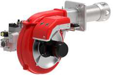
The FBR X GAS XP 60 CE TC EVO (_41) represents mid-range industrial capacity with 250mm nozzle diameter and power output spanning 232-630kW. This model operates on 3-phase electrical supply (380-415V typical in Singapore facilities). When diagnosing issues on this unit, verify that incoming electrical supply maintains symmetrical phase voltage within ±3% tolerance. Voltage imbalance exceeding this threshold causes control relay chatter and intermittent ignition failures. Additionally, the 250mm nozzle diameter requires specific pressure testing: gas pressure should read 60-80mbar at the fuel inlet during operation. Below 60mbar, flame lift-off occurs; above 80mbar, burner noise and instability increase significantly.
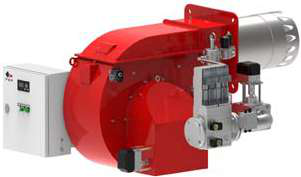
Higher-capacity systems like the FBR GAS XP 80/M CE-LX4 TL Cl. 4 (_41) and FBR GAS XP 80/2 CE-LX4 TL Cl. 4 (_41) both feature 385mm nozzles and reach 850kW maximum capacity. These industrial-grade burners require more rigorous diagnostic discipline. The 385mm nozzle diameter demands precise fuel atomisation; any degradation in nozzle surface finish causes combustion inefficiency and excess emissions. Inspection should include visual assessment of the nozzle orifice under magnification—acceptable nozzles show clean, sharp edge geometry. Worn nozzles display rounded or eroded edges, increasing fuel droplet size and reducing combustion completeness.
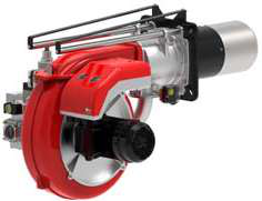
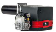
For smaller installations, the FBR GAS X2/M CE-LX4 TC Cl. 4 (_31) and FBR GAS X2/M CE TC (_31) deliver 93kW maximum on single-phase supply (230V). Both feature identical 90mm nozzles but operate at different minimum power levels (23.7kW vs 17.4kW respectively). The lower minimum threshold on the latter model provides greater turndown capability—the ratio of maximum to minimum power output. Extended turndown ratios (4:1 or greater) require more sophisticated flame detection and airflow management. When diagnosing turndown-related issues, systematically test the burner across its full operating range, recording flame appearance, gas pressure, and combustion air temperature at 25%, 50%, 75%, and 100% load points.
Real-World Application Examples: Systematic Fault Resolution
Scenario 1: Intermittent Flame Extinction on High-Capacity Burner
A food processing facility in Singapore operating an 850kW FBR GAS XP 80/2 burner experiences flame dropout every 15-20 minutes during continuous operation. Initial inspection reveals normal flame appearance and stable gas pressure during operation. The issue emerges only after extended run time. Diagnostic conclusion: thermal accumulation in the ignition electrode housing creates insulation breakdown. Solution involves allowing equipment to cool, cleaning the electrode assembly with compressed air to remove combustion residue, and adjusting electrode spacing to manufacturer specification (typically 3mm ±0.5mm). Post-repair verification confirmed stable operation for 72-hour continuous run without dropout.
Scenario 2: Failed Ignition on Start-Up (Mid-Range Unit)
An industrial laundry facility's FBR X GAS XP 60 CE TC EVO burner fails to ignite despite normal electrical supply. Control panel shows ignition lockout after three attempted cycles. Technician checks: (1) spark at ignition electrode—confirmed present with blue spark visible, (2) gas supply pressure—reads 45mbar, below 60mbar minimum threshold, (3) gas supply valve—physically opens properly but downstream regulator shows signs of diaphragm rupture. Diagnosis: Faulty pressure regulator. Replacement with correct regulator (rated for system's maximum fuel volume) restored ignition success. This scenario emphasises that apparent ignition failures often originate in fuel supply components rather than the burner itself.
Scenario 3: Excessive Emissions on Variable-Load Application
A chemical processing plant operating two FBR GAS X2/M burners at reduced output (40% of rated capacity) reports elevated NOx emissions during efficiency audits. Both burners physically operate normally with stable flame, but combustion analysis shows incomplete fuel oxidation. Root cause: At reduced load, combustion air volume drops proportionally, but the 90mm nozzle continues atomising fuel for previous full-load conditions. This fuel-rich condition increases emissions and reduces efficiency. Solution involved replacing one 90mm nozzle with a smaller nozzle diameter optimised for the facility's typical operating point, and adjusting air damper settings for improved air distribution at partial load.
Selection Criteria and Best Practices for Burner Troubleshooting
Effective burner troubleshooting requires systematic methodology rather than trial-and-error approaches. Begin with equipment documentation: obtain original specification sheets, electrical schematics, and service records. These documents provide baseline performance data and maintenance history revealing patterns.
Invest in proper diagnostic instrumentation: combustion analysers measuring O2, CO, and NOx; multimeters for electrical circuit verification; manometers for pressure measurement; and combustion tachometers for airflow assessment. Without these tools, diagnosis becomes speculative.
Establish baseline parameters specific to your burner model. For instance, the FBR burner range sold throughout Singapore typically maintains these parameters: gas pressure ±5mbar from setpoint, combustion air temperature stability within ±5°C, and ignition delay under 2 seconds from fuel valve opening. Any variance from these baselines indicates fault development.
Implement preventive maintenance schedules: monthly visual inspection of nozzles and electrodes, quarterly cleaning of fuel strainers, and annual replacement of control components like CBM relays and connectors. The CBM 7 pole male connector and supporting electrical components experience wear from thermal cycling and merit periodic replacement before failure occurs.
Optimising Control Circuit Reliability
Control circuits represent the intelligence governing safe burner operation. Modern industrial burners integrate automatic controls that sequence fuel and air delivery, monitor flame presence, and execute emergency shutdown when unsafe conditions develop. The CBM Relay TMG 740-3 exemplifies this approach, providing automatic control for intermittent-duty gas and mixed fuel burners with flame detection through ionisation electrodes, UV cells, or infrared oscillation detection.
When troubleshooting control issues, verify control power supply voltage stability using a quality multimeter. Fluctuations exceeding ±10% of nominal supply cause relay chatter and unpredictable burner behaviour. Ground connections warrant particular attention—resistance should measure below 1Ω from control earth to the burner frame. Corroded ground connections create intermittent faults that frustrate diagnosis.
Conclusion and Professional Support
Gas burner troubleshooting blends theoretical understanding with practical diagnostic discipline. By systematising your approach across fuel delivery, ignition, flame stability, and control circuits, you'll identify 95% of common faults without costly external service calls. However, complex issues involving electronic control modules, flame detection sensors, or pressure regulator failures often benefit from manufacturer technical support.
At 3G Electric, we've served Singapore's industrial sector since 1990, supplying comprehensive burner and combustion equipment alongside technical expertise. Our team maintains deep product knowledge across the FBR and CBM equipment lines featured in this guide. Whether you're troubleshooting an existing installation or selecting replacement components, contact 3G Electric for technical consultation. We provide equipment specification verification, diagnostic support, and rapid procurement of replacement parts including nozzles, electrodes, control relays, and electrical connectors. Reach out to our Singapore team to discuss your specific burner system challenges—our experienced technicians are ready to support optimal combustion system performance.