Understanding Burners & Combustion UV Detection Systems
Flame detection in modern industrial burners relies on ultraviolet (UV) sensor technology to verify combustion is occurring safely and continuously. When a burner fires, the UV detector responds to the spectral signature of the flame, sending a signal to the safety relay module which confirms the presence of fire. This closed-loop system prevents dangerous fuel accumulation and uncontrolled combustion. For maintenance teams across Southeast Asia, understanding how UV detection integrates with your burner control system is essential—especially when safety interlocks fail or false shutdowns occur.
At 3G Electric, we have distributed industrial combustion equipment for over 35 years. During that time, we have seen UV detection failures account for approximately 15-20% of all unplanned burner shutdowns in the region. Most of these failures stem not from detector age alone, but from installation errors, optical contamination, or relay sensitivity misconfiguration. By learning to diagnose these issues systematically, your team can reduce downtime and maintain safe, stable combustion in critical heating and process applications.
Section 1: UV Detector Spectral Response and Optical Contamination Diagnostics
Identifying UV Cell Degradation and Window Fouling
The Combutech UV1p detection cell represents modern UV flame detection technology, with spectral response in the 185–260 nm range—precisely tuned to detect the ultraviolet emissions of hydrocarbon flame fronts. However, even premium detectors like the UV1p are vulnerable to optical contamination from combustion by-products, dust accumulation, and thermal cycling.
Optical contamination progression:
- Week 1–2 (Minor soiling): Detector sensitivity drops 10–15%, but flame signal remains stable.
- Week 3–4 (Moderate fouling): False flame loss signals appear during flame stabilization; nuisance shutdowns increase.
- Month 2+ (Heavy accumulation): Detector fails to respond to normal flame, forcing manual reset cycles or burner lockout.
In Southeast Asian tropical climates, humidity and salt-laden air (especially near coastal facilities) accelerate window degradation. The Combutech UV1p's IP65 rating provides protection, but the optical window itself remains exposed to the flame environment.
Diagnostic procedure for optical contamination:
1. Visual inspection: Turn off the burner. Using a flashlight, observe the UV detector window (typically a sapphire or borosilicate lens). Look for white, gray, or yellow deposits. Any visible soiling indicates contamination.
2. Response time test: With the burner running at normal load, manually block the detector line of sight using a non-flammable card. The flame relay should trip within 2–3 seconds. If delay exceeds 4 seconds, contamination is likely restricting UV photon flux.
3. Spectroscopy check (if available): Some maintenance teams in larger plants use portable spectroscopy tools. A healthy UV1p cell should show a clear absorption peak at 254 nm. Reduced peak amplitude (>20% lower than baseline) suggests optical degradation.
4. Cleaning protocol: Use only soft lens paper and isopropyl alcohol (70% concentration). Wipe gently in circular motions. Do not use abrasive cloths or high-pressure air, which can scratch the optical surface. Allow 10 minutes air-dry time before restarting.
Prevention: Establish a monthly inspection schedule. In dusty environments (cement, steel mills), increase to bi-weekly checks. Install flame detector air purge kits if your budget permits—these direct clean, compressed air around the lens, extending cleaning intervals by 50–60%.
Section 2: Safety Relay Module Response and Electrical Diagnostics
Troubleshooting Flame Relay Sensitivity and Reset Failures
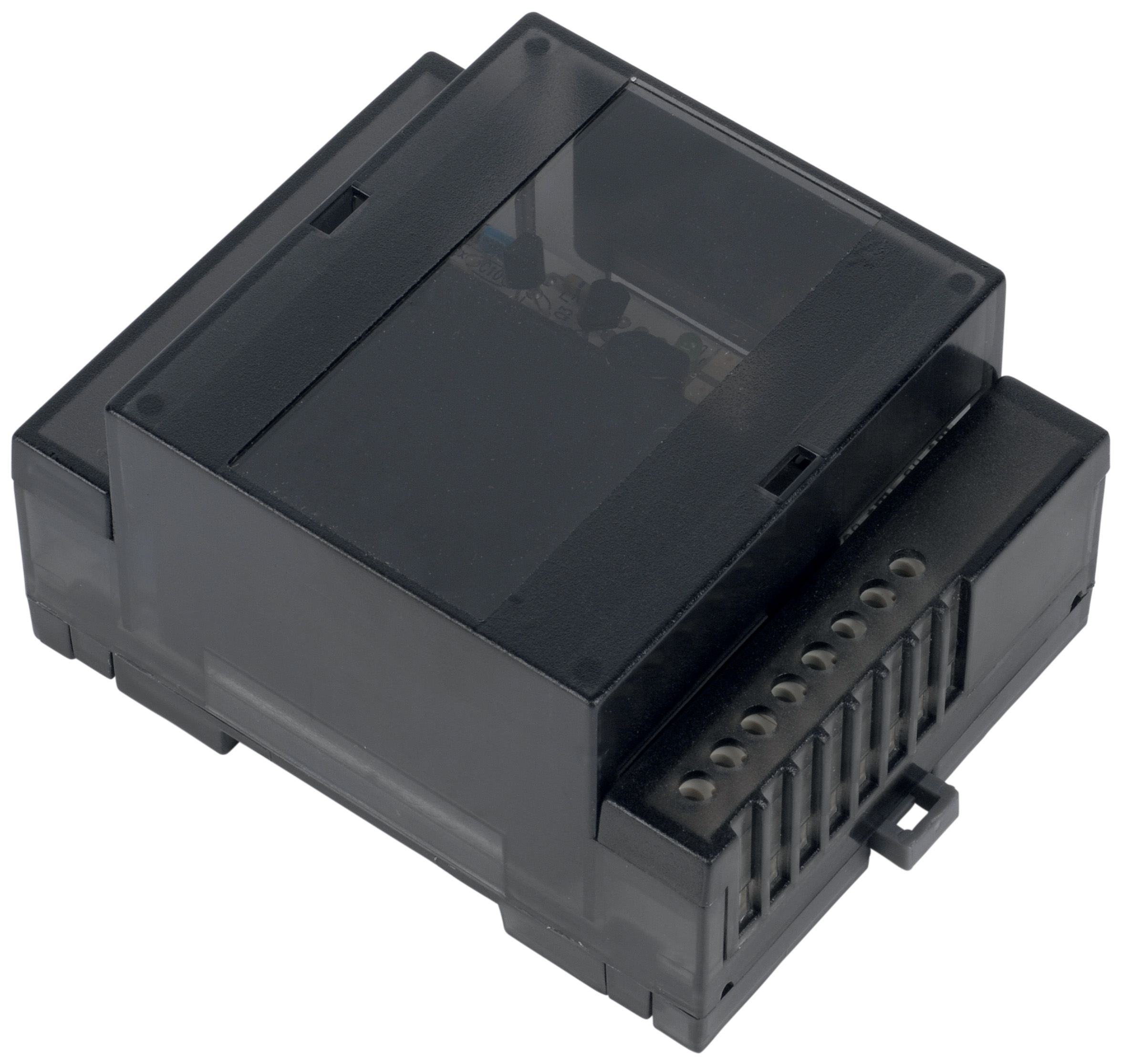
The Combutech Flame relay CF1 is engineered to accept signals from multiple UV detectors (up to 10 cells on a single line) and translate them into a go/no-go electrical contact for the burner control circuit. The CF1's 1 A @ 250 VAC and 1 A @ 30 VDC ratings suit most industrial burner applications; however, relay sensitivity drift and reset circuit failures are common failure modes in the field.
Why relay sensitivity deteriorates:
- Input signal noise from nearby high-voltage motor starters or frequency drives (common in Southeast Asian plants with variable-speed equipment).
- Aging input filter capacitors in the relay module (typical lifespan 5–7 years in tropical humidity).
- Misadjustment of potentiometer sensitivity controls during commissioning—difficult to reverse without schematic knowledge.
- Intermittent wiring connections in the UV detector loop, causing marginal signal levels that trigger false resets.
1. Measure input signal voltage: With the burner running, use a digital multimeter (DC setting) to measure the voltage at the relay input terminals. A healthy UV1p signal typically reads 4–8 VDC during flame. Readings below 2 VDC indicate either detector contamination (Section 1) or poor wiring connections.
2. Check signal stability: Set the multimeter to AC voltage (mV range). Excessive AC ripple (>0.5 VAC) on the DC signal indicates noise. If present, inspect all wiring for loose connections, damaged insulation, or proximity to high-current circuits. Reroute detector wiring away from motor control lines if necessary.
3. Verify reset delay: This is critical in Southeast Asia's humid environment. The CF1 relay should return to standby (safe) state within 500 ms of flame loss. If reset time exceeds 2 seconds, the internal relay contacts may be sticking—usually from humidity-induced oxidation. Perform a "dry cycle" test: apply 24 VDC power for 10 seconds, then remove power; repeat 5 times. If reset time improves, contact oxidation is present; the relay may be nearing end-of-life.
4. Load contact resistance: Once the relay trips (flame detected), measure resistance across the output contacts using an ohmmeter (burner control circuit powered off). Resistance should be <0.2 Ω. If measured resistance is >0.5 Ω, contact corrosion is limiting current flow, and the relay output may not reliably energize downstream solenoid valves or ignition circuits.
5. Isolation test: Disconnect the UV detector wiring from the relay input. Apply a variable DC voltage supply (0–10 VDC) to the relay input terminals and measure voltage at which the output contacts close ("pick-up threshold") and open ("drop-out threshold"). Typical specification: pickup 3.5 VDC, dropout 1.5 VDC. If measured thresholds deviate >20% from specification, the relay sensitivity amplifier has degraded and replacement is recommended.
Sensitivity adjustment (if available on your model):
Some CF1 relay variants include an adjustable sensitivity potentiometer. Do not adjust without a reference signal generator or direct instruction from your burner control system manufacturer. Excessive sensitivity leads to false flame detection (fire when no flame exists); insufficient sensitivity causes delayed flame confirmation or nuisance shutdowns. If adjustment is necessary:
- Back the potentiometer to full counterclockwise (minimum sensitivity).
- Apply the smallest UV detector signal you expect to see (typically 2–3 VDC).
- Slowly rotate the potentiometer clockwise until the relay output contact just closes.
- Document the final potentiometer position.
- Do not disturb this setting without re-running the test.
Section 3: Integration Troubleshooting—Burner Equipment and Relay Performance
Matching Detector Response to Burner Flame Characteristics
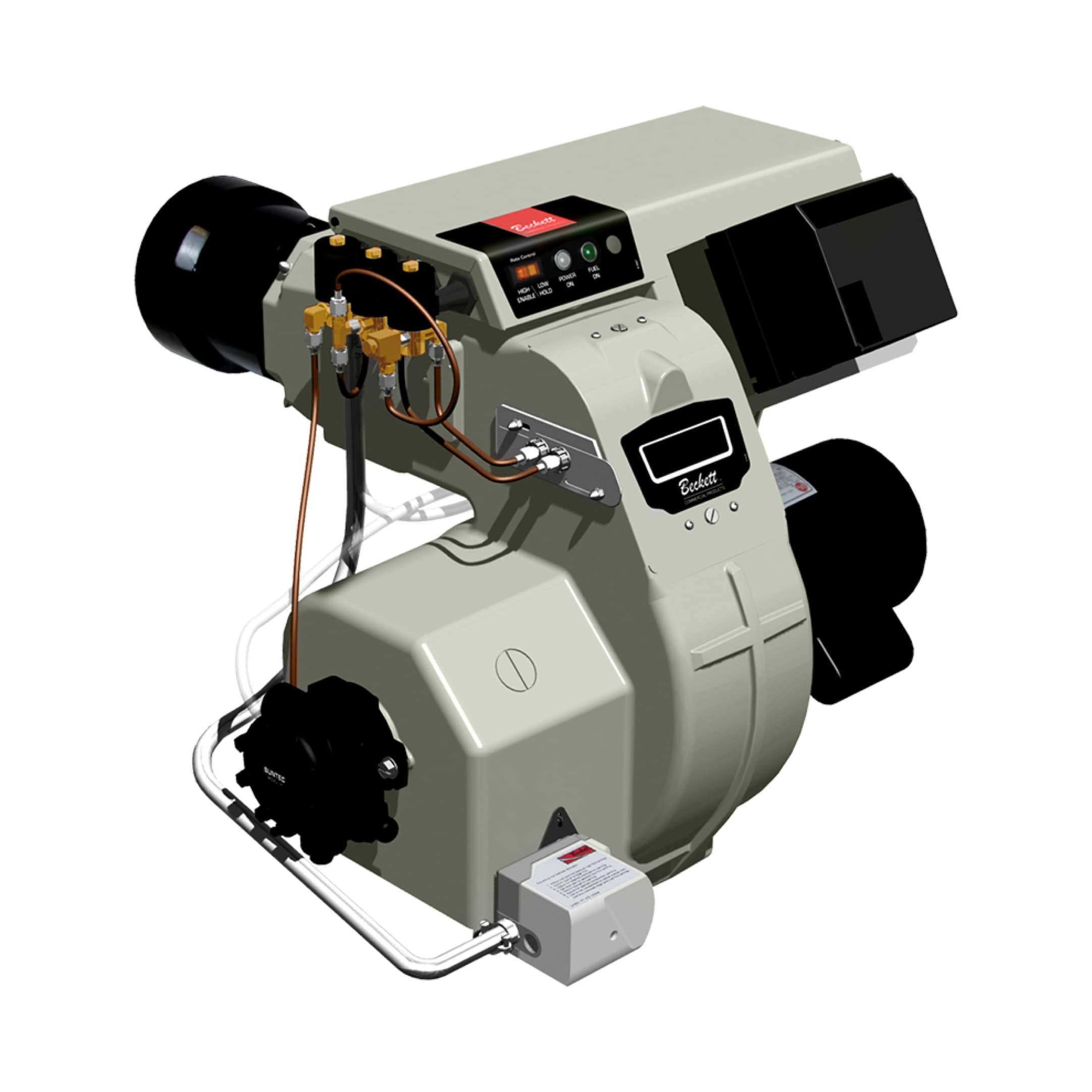
Not all flame detection problems originate in the UV detector or relay. Burner design, fuel type, and combustion intensity directly affect the signal strength reaching your detection system. For example, the Beckett CF3500 Oil Burner (17–35 GPH capacity) generates a characteristic flame spectrum dependent on nozzle spray pattern, air supply ratio, and fuel quality. The FBR HI-GAS P550/M gas burner (2325–6395 kW output) produces a very different UV signature due to its high-velocity gas flame and advanced combustion chamber design.
When integrating UV detection with industrial burners across Southeast Asia, maintenance teams must understand that a reliable detector in one burner application may struggle in another without proper siting and flame characterization.
UV signal strength assessment by burner type:
| Burner Type | Typical Flame UV Intensity | Detector Distance (Optimal) | Signal Stability Issues |
|---|---|---|---|
| Oil atomizer (10–35 GPH) | Medium (4–7 VDC signal) | 100–150 mm from flame | Intensity varies with nozzle clogging; monitor monthly |
| Gas burner – fixed power | High (7–10 VDC signal) | 150–250 mm from flame | Very stable; few noise issues |
| Gas burner – modulating | Variable (2–10 VDC, dynamic) | 200–300 mm from flame | Signal fluctuates during load change; relay must tolerate 30% ripple |
| Multi-fuel burner (oil + gas) | Medium-to-high (4–9 VDC) | 150–200 mm from flame | Switchover spikes; confirm relay hysteresis 1.5 V minimum |
Commissioning check for new or relocated burners:
1. Establish baseline signal: Start the burner at full load (no modulation). Measure the UV detector signal voltage over 5 minutes. Record the minimum and maximum readings. If variation exceeds ±1 VDC, the detector siting is suboptimal.
2. Vary combustion air supply: Gradually reduce the air supply using the burner's air shutter or fan damper. Observe how the UV signal changes. In a properly sited detector, signal should remain >3 VDC even at 80% air-lean condition. If signal drops below 2 VDC before reaching the air-lean limit, move the detector closer to the flame or check for optical contamination.
3. Flame loss simulation (cold restart test): Switch the burner off and back on immediately. The burner control sequence should command ignition, and the UV relay must confirm flame within 3 seconds. If confirmation is delayed or missing, the detector siting may be insufficient for fast flame establishment. Increase detector sensitivity (via potentiometer, if adjustable) or relocate the detector to a clearer flame view.
Integration with oil and gas systems:
When using the FBR GAS/M CE D2"S-F-50 progressive burner (485–4070 kW, modulating), UV detector signal changes continuously during load modulation (from pilot flame to full fire). The relay response must accommodate this dynamic signal variation without false shutdowns. Test procedure:
- Set the control system to modulating mode.
- Command the burner through a full load cycle (pilot → 20% → 50% → 100% → 50% → 20% → pilot).
- Monitor the UV relay output contact closure throughout the cycle. There should be no momentary opens or chatter.
- If relay chatter occurs during modulation transitions, either increase the relay response filter time constant (delay acceptance of signal dropout by 200–500 ms) or reduce detector sensitivity slightly to eliminate noise pickup during flame intensity changes.
Section 4: Preventive Maintenance and Emergency Recovery Procedures
Scheduled Maintenance Schedule for Southeast Asian Climate
Tropical and humid conditions in Southeast Asia demand more frequent UV detection maintenance than temperate regions. Temperature swings from 28°C daytime to 18°C at night create condensation cycles that accelerate oxidation of relay contacts and window fouling.
Recommended maintenance intervals:
| Task | Frequency | Est. Duration | Notes |
|---|---|---|---|
| Visual inspection (window soiling, wiring condition) | Monthly | 15 min | Non-invasive; flags issues before sensor drift |
| Soft-brush cleaning of detector window | Every 4–6 weeks | 10 min | Use lens paper + 70% IPA only |
| Signal voltage trending (multimeter test at full load) | Quarterly | 20 min | Document values; establish trend line |
| Relay contact resistance measurement | Every 6 months | 15 min | Ohmmeter test; replace if >0.5 Ω |
| Full detector + relay system test (signal simulation or cold start) | Annually | 45 min | Confirms end-to-end functionality before heavy heating season |
| Relay replacement (preventive) | Every 5–7 years | 30 min | Even if functional; avoids surprise failures in critical season |
Emergency recovery procedure (nuisance shutdowns mid-operation):
When a running burner unexpectedly shuts down due to "flame loss," follow this rapid diagnostic:
1. Immediate safety action: Ensure the burner control system has locked out fuel supply. Do not attempt to restart immediately—allow 5 minutes for fuel vapor purge.
2. Quick visual check: Look at the UV detector window. If heavily soiled (visible white or yellow deposits), proceed to Section 1 cleaning procedure. This resolves ~40% of emergency shutdowns.
3. Check for loose connectors: Trace the UV detector wiring to the relay module. Gently tug on each connector and terminal. Corrosion or vibration-induced looseness is common in machinery-heavy environments. Reseat all connectors firmly.
4. Measure DC signal (30-second test): With the burner still off, manually apply low voltage (3–5 VDC from a bench power supply) to the relay input. The relay output should energize within 1 second. If no response, the relay has failed—skip to replacement.
5. Restart burner and observe first 30 seconds: Command the burner to start. If it runs beyond the initial ignition sequence (15–20 seconds) without shutdown, the system has recovered—likely the quick connector reseat fixed a marginal connection. If shutdown recurs within 5 minutes, advance to full diagnostics per Section 2.
Parts procurement for field replacement:
Maintain stock of critical UV detection components at your facility:
- 1–2 replacement Combutech UV1p detection cells (COB02082): Each burner should have one spare stored in a dry cabinet.
- 1 replacement Combutech Flame relay CF1 module (COB02030): Central storage; order replacement within 24 hours of installation if failure occurs.
- Connector terminals and shielded twisted-pair wiring: Keep a kit of spare terminals and 10 meters of shielded cable on hand for emergency repairs.
As a Southeast Asian distributor partner, 3G Electric stocks these components and can expedite shipment to your facility within 2–3 business days. Contact our technical support team to establish a preferred spare parts account.
Documentation and Trend Analysis
Maintenance teams that systematically document UV detector and relay performance outperform reactive troubleshooters by preventing 60–70% of unplanned shutdowns. Create a simple spreadsheet or log:
Monthly Detector Log Example:
- Date: [Date]
- Burner Model: [e.g., Beckett CF3500 or FBR HI-GAS P550/M]
- UV Signal at Full Load: [Voltage, VDC]
- Window Condition: [Clean / Light Soiling / Heavy Soiling]
- Relay Reset Time: [ms]
- Notes: [Any shutdowns, unusual behavior, or actions taken]
After 6 months of data, you will see clear patterns: signal dropping by 0.5 VDC per month indicates approaching maintenance need; relay reset time creeping from 200 ms to 600 ms signals imminent relay failure. These trends allow you to schedule replacement during planned maintenance windows rather than emergency outages.
Conclusion: Building Reliable Combustion Control in Southeast Asia
Burners & Combustion systems depend critically on fast, accurate flame detection. UV flame detection, integrated with safety relay modules like the Combutech CF1, provides the feedback loop that prevents dangerous misfires and maintains efficient combustion across industrial oil and gas burners. In Southeast Asia's demanding tropical environment, proactive diagnostics and scheduled maintenance are not optional—they are essential to avoiding costly downtime and safety incidents.
3G Electric has supported maintenance teams across the region for over 35 years with industrial combustion equipment, spare parts, and technical guidance. Whether you operate a Beckett oil burner, FBR progressive gas burner, or integrated dual-fuel system, the diagnostic procedures outlined in this guide will help your team isolate UV detection failures, verify relay response, and restore reliable flame monitoring. Start with monthly visual inspections and quarterly signal measurements, escalate to full system testing annually, and do not hesitate to contact your equipment supplier when signal degradation trends become apparent.
Reliable combustion control begins with understanding your detection system. Master these diagnostics, and your burners will run safely and efficiently for years to come.