Gas Burner Control System Lockouts: Troubleshooting Non-Volatile Safety Shutdowns in Singapore
Gas burner control systems are engineered with multiple safety layers, and one of the most important is the non-volatile lockout mechanism. When a control system detects an unsafe condition—whether flame failure, improper ignition sequencing, or pressure anomalies—it automatically enters a lockout state that requires manual intervention to reset. Understanding these lockout conditions and how to troubleshoot them is critical for industrial professionals managing burner systems across Singapore's manufacturing, hospitality, and energy sectors. This guide provides a systematic approach to diagnosing lockout failures and restoring safe operation.
What is a Non-Volatile Lockout and Why Does It Matter?
A non-volatile lockout is a safety mechanism built into modern burner control systems that prevents repeated automatic restart attempts when a potentially dangerous condition is detected. Unlike a simple reset that clears immediately, a non-volatile lockout persists even after power cycles—it requires deliberate manual intervention to clear. This design philosophy prioritizes personnel safety by preventing uncontrolled burner reignition attempts that could create hazardous conditions.
When a control system enters lockout, it typically means one of three primary fault categories has been triggered: flame supervision failure (the control cannot detect or verify flame presence), ignition sequence violations (the control failed to establish flame within the designated time window), or safety interlocking failures (required pre-start conditions were not met). The lockout state itself is not a defect—it is the system functioning exactly as designed, which means the troubleshooting process focuses on identifying why the lockout occurred, not how to bypass it.
In Singapore's industrial environment, where burner systems operate continuously in demanding applications like catering equipment, boilers, and steam generation, lockouts often indicate subtle degradation rather than catastrophic failure. A thermocouple losing sensitivity, a flame detector accumulating deposits, or a pressure regulator drifting out of specification—each can trigger legitimate lockouts that demand diagnostic attention rather than simple reset procedures.
Technical Architecture of Modern Burner Control Systems
To troubleshoot lockouts effectively, you must understand the functional architecture of the control system. Modern gas burner controls typically integrate five core functional blocks: the ignition circuit, the flame supervision circuit, the solenoid valve control circuit, the air pressure/fan management circuit, and the safety interlocking logic.
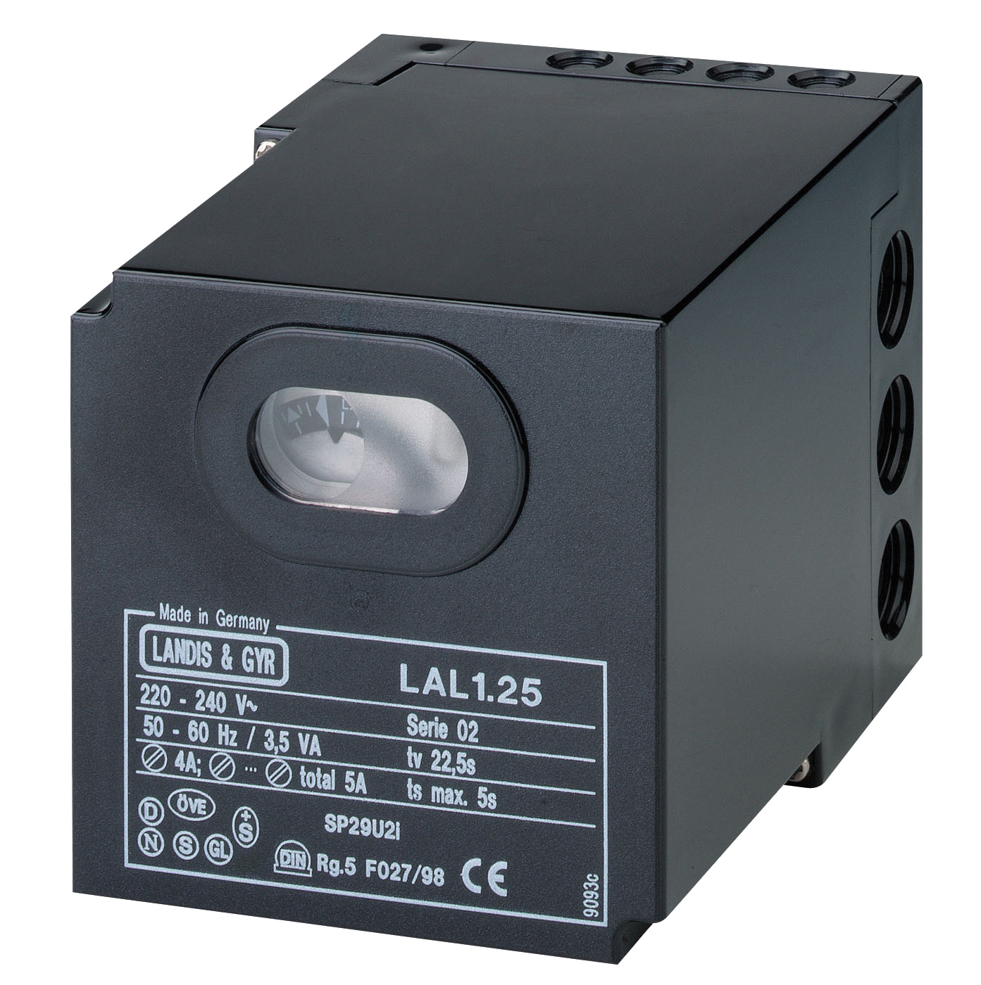
The CBM Relay SM 592.2 and CBM Relay CM391.2 represent the Eurobox series architecture, designed specifically for atmospheric and fan-assisted burners with intermittent operation. These control systems perform continuous diagnostics during the startup sequence: they verify that solenoid valves open correctly, confirm ignition initiation, monitor for flame establishment within the specified time window (typically 3-8 seconds), and then sustain flame supervision throughout the run cycle.
When lockout occurs, the control system has detected that one of these verification steps failed. The specific timing of the failure within the startup sequence—before ignition, during ignition ramp, or during flame establishment—narrows the diagnostic focus significantly. A lockout occurring immediately upon start attempt suggests either ignition circuit failure or solenoid valve malfunction. A lockout occurring 2-3 seconds into startup suggests flame detection failure. A lockout occurring after sustained operation suggests flame supervision sensor degradation.
The CBM Minisit gas control block incorporates pressure regulation, temperature control, and thermoelectric flame supervision in a compact integrated unit suitable for smaller boilers and stoves. Understanding your specific control architecture—whether integrated multifunctional or modular relay-based—is essential because restart procedures and diagnostic approaches differ between system types.
Systematic Diagnostic Procedure for Lockout Conditions
The diagnostic approach follows a structured sequence that progressively eliminates subsystems. Begin by documenting the exact failure mode: Does the ignition electrode spark? Does the solenoid valve click and energize? Does the pilot light ignite? Does the main burner ignite? At what point in the sequence does the control enter lockout? These observations establish whether the failure is upstream (ignition/fuel delivery) or downstream (flame detection/supervision).
Stage 1 – Ignition Circuit Verification: Confirm that the ignition transformer is energizing and the high-voltage ignition circuit is functional. You should observe spark at the ignition electrode during startup. If spark is absent, verify transformer primary voltage (typically 230V AC) and check for any fused circuits. Electrode gap should be within 2.5–3.5mm; excessive gap or electrode fouling prevents reliable spark.
Stage 2 – Fuel Delivery and Solenoid Valve Function: Confirm that the main solenoid valve energizes (you should hear an audible click) and that gas flows to the burner during startup. If the valve does not energize, verify control signal output from the relay and check 24V DC circuit integrity. If the valve energizes but gas does not flow, the issue is external to the control system (blocked line, regulator failure, or fuel supply interruption).
Stage 3 – Flame Detection Sensor Assessment: This is the most common source of lockout failures in established systems. The flame supervision circuit relies on sensors to confirm flame presence. Common sensor types include infrared detectors (like the CBM IRD 1010 blue cell for oil burners), phototransistor flame sensors, and thermoelectric devices. Inspect the sensor for deposits, corrosion, or physical obstruction. If using an infrared sensor, confirm the optical path to the flame is unobstructed. Sensor contamination is the leading cause of false lockouts in Singapore's tropical environment with high humidity and particulate exposure.
Stage 4 – Control Unit Reset Procedure: Once you have confirmed that the burner hardware (ignition, fuel delivery, and flame supervision) is functionally intact, proceed with the manual reset procedure specific to your control system. Most modern controls require a brief power cycle or a dedicated reset button activation. Consult your specific control model documentation for the exact procedure. If lockout recurs immediately after reset, the underlying fault has not been resolved—do not continue attempting resets, as this may mask dangerous conditions.
Real-World Application Scenarios in Singapore
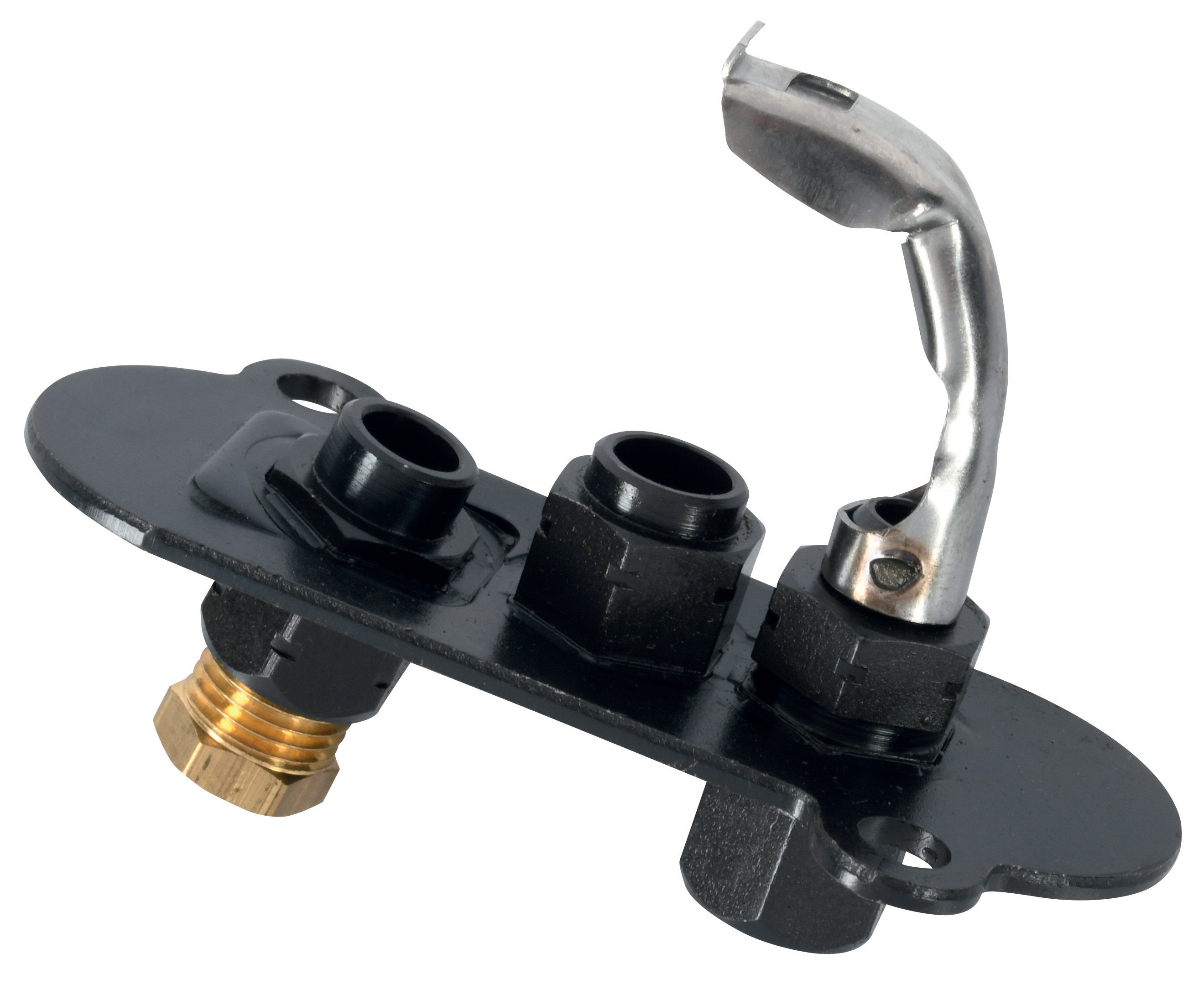
Singapore's industrial landscape presents specific burner control challenges. A large hotel kitchen with continuous-duty catering equipment experienced intermittent lockouts on their main cooking range after 18 months of operation. Initial diagnosis revealed a universal pilot light with fouled thermocouple connection—corrosion from steam and salt aerosol in the kitchen environment degraded the thermoelectric output below the threshold required by the control relay. Replacement with a corrosion-resistant variant and protective shielding eliminated the lockouts.
A food manufacturing facility operating a steam boiler with a CBM Relay GR1 oil burner control experienced repeated lockouts during monsoon season. Investigation revealed that ambient humidity had caused moisture ingress into the control enclosure, degrading the electronic components' insulation resistance. Improved enclosure sealing and environmental monitoring resolved the issue—demonstrating that control system reliability depends on proper installation environment, not just component selection.
A commercial laundry facility using a drying system with intermittent burner operation encountered lockouts following a brief power surge. Although the burner itself sustained no damage, the control relay required replacement; the surge had degraded the solid-state components' tolerance characteristics without causing immediate failure. This scenario highlights the importance of surge protection in Singapore's industrial electrical environment.
Selection and Maintenance Best Practices
To minimize lockout incidents, implement preventive maintenance focused on the subsystems most prone to degradation. Flame supervision sensors require quarterly inspection in high-particulate environments and biannual inspection in cleaner applications. Thermocouples should be tested annually for output stability; replacement is more cost-effective than troubleshooting suspected thermocouple faults. Solenoid valves benefit from functional testing (confirming open/close response) on an 18-month cycle.
When specifying replacement controls, match the system type precisely to your burner application. Atmospheric burner systems require controls like the Eurobox CM/SM series; forced-draught burners require the CBM Relay VM 41 Eurogas architecture. Integrating a control subsystem rated for the wrong burner type leads to nuisance lockouts and safety complications.
Environmental protection deserves emphasis: ensure control enclosures are rated for your installation location's humidity and temperature range. In Singapore's tropical maritime environment, IP65-rated enclosures with internal moisture management are essential for reliability. The CBM Base for GE 733 relay base and similar mounting solutions provide proper environmental isolation when installed correctly.
Conclusion and Next Steps
Non-volatile lockouts are sophisticated safety mechanisms, not equipment failures. Effective troubleshooting requires systematic diagnostic methodology that progresses from observable behavior through subsystem verification to root cause identification. By understanding the control system architecture, following structured diagnostic procedures, and implementing preventive maintenance, you can minimize lockout incidents and maintain safe, reliable burner operation throughout your industrial facilities in Singapore.
If you encounter persistent lockout conditions that do not resolve through standard troubleshooting, or if you need to upgrade aging burner control systems with modern safety architecture, the team at 3G Electric can provide expert guidance. We have been Singapore's trusted distributor of industrial burner controls since 1990, and our technical specialists understand the unique environmental and operational demands of tropical industrial burner applications. Contact us to discuss your specific control system requirements or to arrange a facility assessment of your existing burner installations.