Understanding Fuel Nozzle Maintenance & Service Fundamentals
Fuel nozzles are the critical interface between your fuel supply system and combustion chamber. At 3G Electric, we've supported global industrial operations for over 35 years, and we've learned that most combustion failures trace back to inadequate Maintenance & Service protocols for these essential components.
The flat jet nozzles used in modern burner systems—like the CBM Flat jet nozzle HP 1/4"M BSPT index 25 angle 15° and CBM Flat jet nozzle HP 1/4"M BSPT index 055 angle 15°—operate under extreme pressure and temperature conditions. Without proper Maintenance & Service procedures, these nozzles accumulate carbon deposits, experience spray pattern degradation, and ultimately fail.
Maintenance teams must understand that fuel nozzle performance directly impacts:
- Combustion efficiency and fuel consumption
- Emission compliance (NOx, particulate matter)
- Flame stability and system responsiveness
- Overall burner component lifespan
The challenge is that nozzle degradation occurs gradually. Early signs may be invisible during casual inspection, which is why systematic Maintenance & Service documentation becomes essential for detecting problems before catastrophic failure occurs.
Section 1: Diagnosing Nozzle Performance Degradation & Spray Pattern Issues
Visual Inspection Protocol
Begin every Maintenance & Service cycle with a systematic visual examination. Remove the nozzle safely and inspect for:
Carbon Buildup Patterns: Black or brownish deposits around the nozzle tip indicate incomplete combustion or improper fuel atomization. Light deposits (thin coating) suggest normal operation; heavy crusting means combustion temperature issues or fuel contamination.
Spray Hole Condition: Using magnification, examine the spray holes for blockages. Carbon accumulation preferentially blocks smaller orifices, which distorts the spray pattern. Even partial blockage of one hole in a multi-hole nozzle shifts the spray geometry, creating uneven combustion.
Mechanical Damage: Look for cracks, erosion patterns, or deformation around the spray edge. These indicate either manufacturing defects or thermal stress from operating outside design parameters.
Performance-Based Diagnostics
When visual inspection seems normal but combustion behavior changed, perform these diagnostic tests:
Flame Shape Analysis: Observe the flame geometry during operation. A properly atomized nozzle produces a symmetrical, cone-shaped flame. Asymmetrical or tilted flames suggest:
- Single or multiple blocked spray holes
- Mechanical misalignment of the nozzle in its holder
- Pressure imbalance in multi-fuel systems
Temperature Distribution: Use thermal imaging to map flame temperature. Cold zones indicate fuel reaching the combustion chamber without proper atomization, while hot spots show localized burning where spray holes are blocked.
Maintenance & Service Documentation
Create standardized inspection forms that maintenance teams complete during each service cycle:
- Date, operator name, equipment ID
- Nozzle index number and spray angle
- Visual condition rating (1-5 scale)
- Flame appearance observations
- Emission color at various loads
- Recommended actions (continue, monitor, replace)
This data reveals patterns. For example, if nozzles consistently fail after 8 months in a particular facility, you've identified a systemic problem—possibly fuel contamination or operating temperature—that requires upstream intervention.
Section 2: Fuel Supply Integration & Nozzle Protection Maintenance & Service
Fuel Quality's Impact on Nozzle Health
Nozzle performance depends entirely on fuel quality. Contaminated fuel clogs nozzles faster than any other mechanism. During Maintenance & Service intervals, verify:
Fuel Filtration: Fuel should pass through at least a 10-micron filter before reaching the nozzle. Check filter pressure drop regularly—rising pressure indicates saturation. Many facilities experience nozzle failures because filters run beyond recommended service intervals.
Water Content: Water in fuel accelerates carbon formation and creates deposits that block spray holes. Check fuel tanks during Maintenance & Service cycles. Water settles at the tank bottom; drain several liters and inspect for water droplets. If present, implement dewatering protocols and filter changes.
Fuel Viscosity Monitoring: Temperature changes affect fuel viscosity, which impacts spray atomization. During winter in cold climates, monitor fuel thickness. High-viscosity fuel produces coarse spray patterns that create uneven combustion and carbon buildup.
Storage Tank Maintenance & Service Best Practices
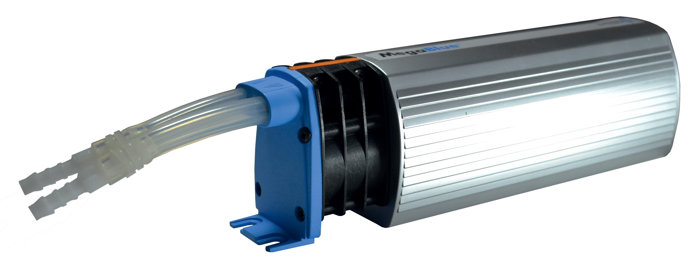
The CBM Megablue reservoir alarm + shut-off X87-813 provides critical tank monitoring. During Maintenance & Service procedures:
Weekly: Verify alarm functionality. The shut-off mechanism must respond to high-level or contamination alerts. Non-responsive alarms allow overfilled tanks, which damage fuel pumps and push water/sediment into distribution lines.
Monthly: Inspect tank exterior for corrosion, especially around seams and drain plugs. Rust penetration compromises tank integrity and introduces ferrous particles into fuel.
Quarterly: Drain tank sediment completely. Even sealed tanks accumulate moisture and particles over time. A 5-minute drain cycle prevents decades of slow contamination.
Annually: Professional tank cleaning removes accumulated sludge, rust scale, and water. Many burner performance issues trace to tanks that haven't been serviced in years.
Expansion Tank Maintenance & Service for Pressure Systems
The CBM Expansion tank inflator battery 2000 mAH is essential for closed-loop fuel systems under pressure. During Maintenance & Service:
Pressure Verification: Check bladder pre-charge pressure monthly. Use the inflator battery to restore pressure if it has dropped. Low pre-charge allows excessive fuel pump pulsation, which creates spray pattern instability and accelerates nozzle wear.
Bladder Inspection: Listen for hissing at the valve stem—indicates bladder rupture. Replace the tank if detected, as a failed bladder causes pressure surges that damage nozzles and seals.
Section 3: Modulating Burner Systems & Advanced Combustion Control Maintenance & Service
Gas Burner-Specific Maintenance & Service Procedures
The FBR BURNER GAS X5/MF TL EL VC LPG represents modern modulating burner technology. These systems achieve efficiency through PID (proportional-integral-derivative) control that continuously adjusts fuel flow. Maintenance & Service requirements differ significantly from simple on-off burners.
Modulation Kit Inspection: If your burner includes the optional modulation kit, verify during every service cycle:
- Probe sensor cleanliness (carbon deposits reduce flame sensing accuracy)
- Electrical connector integrity (corrosion breaks the feedback loop)
- Servo motor operation (sluggish response indicates friction or bearing wear)
- PID tuning parameters (confirm settings match your specific application)
- Fan blade condition (bent or cracked blades reduce air delivery)
- Motor bearing play (excessive play creates air delivery fluctuations)
- Air inlet filter cleanliness (partially clogged filters cause load instability)
- Combustion chamber gasket integrity (leaks introduce uncontrolled air)
Advanced Diagnostic: Multi-Load Performance Testing
Modulating systems require Maintenance & Service verification across the entire operating range. Standard burners function at rated capacity; modulating burners must maintain stable combustion from 20% to 100% load.
Three-Point Load Test: Run the burner at 30%, 65%, and 100% for 5 minutes each. Observe:
- Flame stability (should remain rock-steady with no flicker or size variation)
- Emission color consistency (should remain consistent across load ranges)
- Response time to load changes (should be smooth, not jerky)
- Noise level (unusual buzzing or grinding indicates mechanical issues)
Record baseline performance during initial Maintenance & Service. Compare results during subsequent service cycles to detect degradation trends before failures occur.
Electronic Control System Maintenance & Service
Modulating burners include sophisticated electronic controls. Maintenance & Service for these systems requires:
Display Code Interpretation: Modern burners display diagnostic codes. Maintain a code reference document. Record any codes detected during service, even if the burner returns to normal operation—these codes often predict failures 2-4 weeks before symptoms appear.
Calibration Verification: PID controllers require periodic recalibration. If fuel pressure or air flow has changed, the modulation parameters become mismatched. Professional recalibration during annual Maintenance & Service prevents efficiency loss and flame instability.
Section 4: Preventive Maintenance & Service Planning & Implementation
Establishing Systematic Service Intervals
Effective Maintenance & Service requires planned intervals, not reactive repairs. Based on 35+ years supporting global industrial operations, 3G Electric recommends:
Daily Checks (5 minutes):
- Observe flame appearance and color
- Listen for unusual noises
- Verify alarm system response
- Inspect nozzle exterior visually
- Check fuel filter pressure drop
- Verify all electrical connections
- Remove and examine nozzle condition
- Test expansion tank pressure
- Document all findings
- Deep clean fuel tank sediment
- Professional cleaning of nozzle spray holes
- Combustion air system filter replacement
- Three-point load test on modulating burners
- Complete system disassembly and inspection
- Professional tank cleaning
- Electronic control recalibration
- Nozzle replacement if degradation detected
- Emission testing and documentation
Creating Maintenance & Service Documentation Systems
Maintenance teams that document Maintenance & Service activities discover problems early and optimize replacement intervals. Implement:
Digital Record Keeping: Use spreadsheets or specialized CMMS software to track:
- Service date and technician
- Components inspected and their condition
- Measurements (pressures, temperatures, emissions)
- Parts replaced
- Costs and downtime
- Predicted failure dates
- Do certain components fail repeatedly?
- Are failures clustered in particular seasons?
- Do failures correlate with production increases?
These patterns reveal root causes. For example, nozzle carbon buildup in winter suggests fuel gelling; frequent failures after high-load periods suggest cooling issues; progressive degradation suggests contamination sources.
Spare Parts Strategy: Based on Maintenance & Service history, maintain stock of high-failure components. The critical nozzles—index 25 angle 15° and index 055 angle 15°—should always be available for emergency replacement.
Training & Knowledge Transfer
Sustainable Maintenance & Service depends on trained personnel. 3G Electric recommends:
- Annual training on your specific burner model
- Hands-on workshops for nozzle removal and inspection
- Competency certification for personnel performing adjustments
- Cross-training to prevent knowledge loss from staff turnover
Well-trained maintenance teams recognize subtle degradation signs that casual operators miss, preventing costly failures.