Electrical Measurement & Detection for Maintenance Teams: A Practical Guide to Voltage Testing and Multimetry
Electrical hazards are among the most dangerous threats in industrial maintenance. Every day, maintenance teams and service engineers work with live circuits, power distribution systems, and complex electrical installations across manufacturing facilities, HVAC systems, and pneumatic operations worldwide. Before you touch a wire, test a circuit, or diagnose an electrical fault, you need the right measurement and detection tools—and more importantly, you need to know how to use them safely and accurately. This guide walks you through the practical application of voltage detection and multimetry, two fundamental skills that separate confident technicians from those who take unnecessary risks.
Why Electrical Measurement & Detection Matters in Industrial Maintenance
Electrical diagnostics form the backbone of preventive and corrective maintenance. Whether you're troubleshooting a faulty sensor on a pneumatic compressor, testing voltage across HVAC control boards, or verifying circuit continuity before component replacement, accurate measurement and detection prevent both equipment damage and personnel injury.
The challenge is that electrical hazards are invisible. Unlike a leaking hydraulic line or a grinding bearing, you cannot hear, see, or feel electricity until it reaches dangerous voltage levels. This is why non-contact detection methods have become industry standard—they allow you to identify live circuits from a safe distance before making direct contact with conductors or terminals.
Measurement and detection tools serve three critical functions in maintenance workflows:
- Safety verification: Confirming that circuits are de-energized before work begins
- Fault diagnosis: Identifying voltage drops, phase loss, continuity breaks, and resistance anomalies
- Performance validation: Verifying that repairs are correct and systems operate within specification
The most effective maintenance teams integrate multiple measurement instruments into their diagnostic toolkit rather than relying on a single device. A comprehensive electrical measurement strategy combines non-contact voltage detection with multimetry to create layered protection and diagnostic capability.
Non-Contact Voltage Detection: Safe First-Line Screening
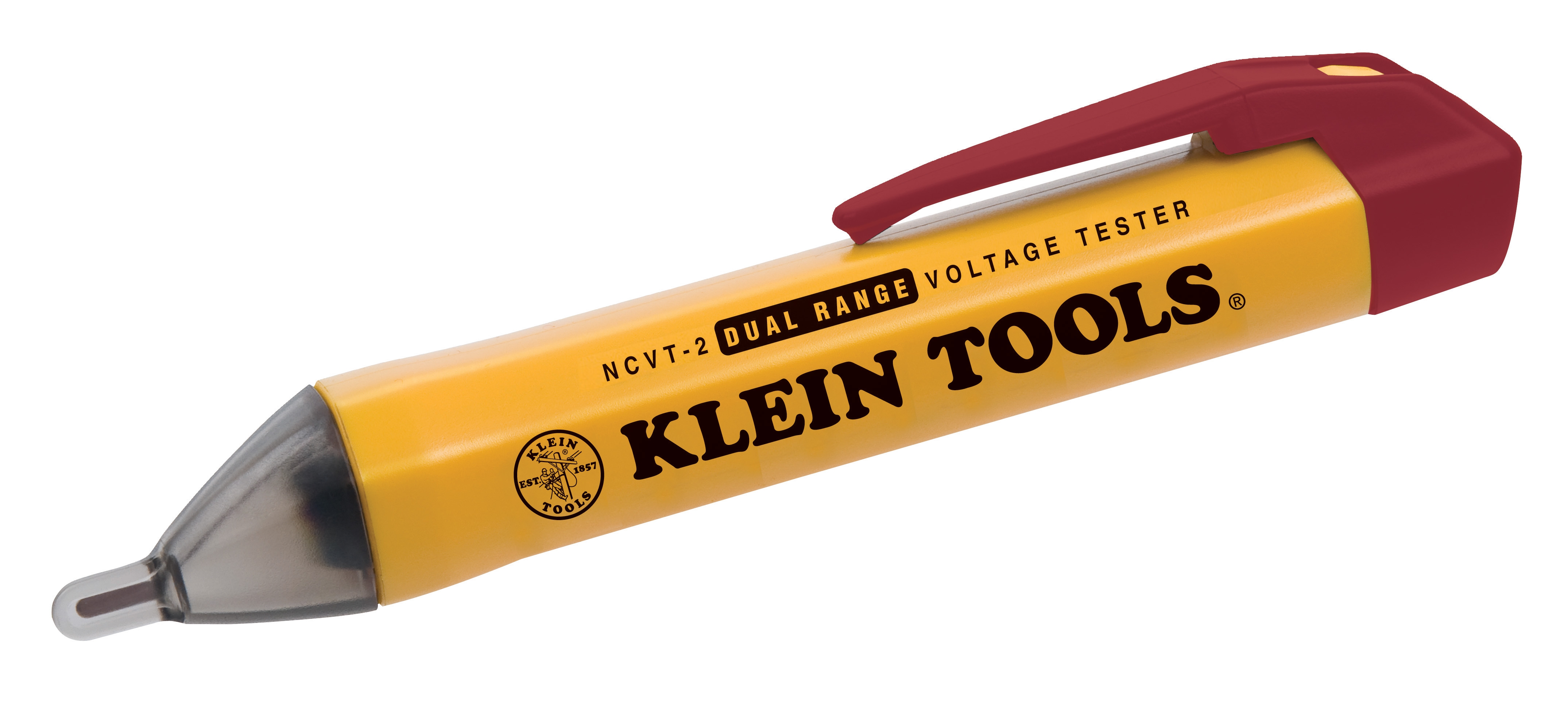
Non-contact voltage detection represents the first critical step in any electrical troubleshooting workflow. These tools identify the presence of electrical potential without requiring direct contact with live conductors—a safety feature that has prevented countless injuries across industrial settings globally.
The CBM Non-contact Voltage Detector employs a dual-range detection system that identifies voltage presence within a 6 mm detection range. This proximity-based approach allows technicians to safely scan electrical enclosures, junction boxes, and component terminals from a safe distance before initiating contact-based testing.
How non-contact detection works: These devices sense the electromagnetic field radiating from energized conductors. When you bring the probe within range of a live wire or terminal, the detector emits an audible alert and visual indicator—typically an LED that illuminates or changes color. The dual-range feature enables detection of both standard voltage levels and lower-voltage circuits, expanding applicability across control systems, sensor networks, and auxiliary circuits.
Practical application sequence:
- Approach the equipment or component cautiously
- Activate the detector and allow the initial calibration
- Systematically scan the area where you plan to work
- If the detector triggers, the circuit is live—step back and de-energize before proceeding
- If no response, the area is likely safe, but verify with contact-based testing before touching conductors
Non-contact voltage detectors are particularly valuable for rapid safety screening in high-density electrical environments—such as motor control centers, distribution panels, and industrial control cabinets—where direct contact testing would be time-consuming and require multiple points of verification.
Digital Multimetry: Precision Measurement and Diagnostic Depth
Where non-contact detection identifies voltage presence, digital multimeters provide quantitative measurement and advanced diagnostics. The CBM Automatic Multimeter MM420 represents the core measurement instrument for industrial technicians, offering both AC/DC voltage measurement and current monitoring capabilities essential for systematic fault diagnosis.
Key specifications of the MM420:
- Maximum AC/DC current measurement: 10 A (high range) and 400 mA (low range)
- 350 mA/250 V fuse protection against accidental overload
- 9V battery operation for portable field deployment
- Automatic range selection in standard mode
Core measurement functions for maintenance applications:
- AC/DC Voltage: Verify power supply levels at device inputs, control transformers, and sensor power rails. Normal industrial systems typically operate at 24 VDC (control circuits), 120 VAC (auxiliary circuits), or 480 VAC (three-phase motors)
- Current Measurement: Monitor motor current draw to identify mechanical overload (excessive current) or winding faults (low current with high impedance). Current measurement also validates that power distribution circuits deliver rated amperage
- Resistance & Continuity: Test wire continuity, verify circuit traces on control boards, and measure component resistance to identify open circuits and ground faults
- Capacitance & Frequency: Advanced models measure capacitor integrity and signal frequency for precision diagnostics
Practical multimeter workflow: Begin by selecting the appropriate measurement range and function. Insert test leads into the correct terminals (voltage/resistance on the common and V-ohm terminals; current on the common and A terminals). Make contact with the test points and read the display. The automatic range-selection feature of the MM420 simplifies this process for technicians managing multiple circuit configurations throughout a shift.
Battery life and fuse integrity are critical—always verify that your multimeter shows adequate battery level before beginning diagnostics, and carry spare fuses appropriate to your device specifications.
Integration with Pressure and Temperature Measurement in Diagnostic Workflows
Industrial equipment rarely fails in isolation. A motor overheating often correlates with elevated pressure in hydraulic systems, which may indicate mechanical friction or blockage. Similarly, electrical control failures frequently stem from environmental conditions—humidity causing corrosion, temperature extremes affecting solid-state components, or air leaks triggering false sensor readings.
Comprehensive maintenance diagnostics integrate electrical measurement with complementary instrumentation. For example, when troubleshooting an HVAC system, simultaneously measure:
- Voltage at the compressor motor (electrical health)
- Pressure across the refrigerant circuit using a pressure gauge
- Temperature at key points using a thermometer or infrared device
This multimodal approach reveals correlations that single-instrument diagnostics miss. A voltage measurement showing normal supply to a compressor, combined with pressure readings below specification, points toward mechanical wear or refrigerant loss—not electrical fault. This distinction determines whether the technician orders replacement parts or focuses on system pressurization.
Similarly, pneumatic system diagnostics benefit from integrated electrical and pressure measurement. Control circuit voltage verification combined with downstream pressure monitoring identifies whether faults originate in electrical signaling or mechanical flow restriction.
Real-World Diagnostic Scenarios for Maintenance Teams
Scenario 1: Motor Won't Start—Electrical or Mechanical?
A three-phase industrial motor fails to start. The maintenance engineer uses the non-contact voltage detector to confirm that power reaches the motor disconnect switch. Then, using the multimeter, they measure voltage at the motor terminals and verify that all three phases are present and balanced (approximately 480 VAC, ±10%). If voltage is correct, the fault is mechanical (seized bearing, blocked load)—not electrical. If voltage is absent or imbalanced, the fault is upstream in the power distribution or motor control circuit. This binary diagnostic path takes minutes rather than hours with a systematic approach.
Scenario 2: Control System Intermittent Failures
A production line experiences sporadic shutdown events. The engineer measures 24 VDC at the control transformer output—nominal. However, when measuring voltage at sensor inputs downstream, readings fluctuate between 18 and 24 VDC. This voltage sag indicates a failing power supply or excessive current draw from connected sensors. A resistance measurement across the control circuit identifies a corroded terminal connection causing intermittent dropout. This diagnosis directly guides repair action: terminal cleaning or replacement.
Scenario 3: Safety Circuit Verification
Before performing maintenance on a pneumatic actuator system, the engineer must verify that control circuits are de-energized and the system cannot inadvertently pressurize. The non-contact detector quickly scans the control cabinet, confirming no voltage at the main supply. The multimeter then verifies zero voltage across the solenoid coil terminals and measures continuity of the emergency stop circuit. Only after confirming these electrical states does the technician proceed with mechanical work.
Best Practices for Safe and Accurate Electrical Measurement
Pre-measurement inspection: Before using any measurement tool, visually inspect test leads for cracks, exposed conductors, or corrosion. Damaged leads can cause shock hazard or measurement error. Replace compromised leads immediately.
Range selection discipline: When measuring voltage, start at the highest available range and work downward. This prevents potential equipment damage from range mismatch. For current measurement, the 10 A range accommodates most industrial circuits; use the 400 mA range only when measuring low-current control signals.
Fuse awareness: The 350 mA/250 V fuse in the MM420 provides overcurrent protection. If a fuse blows, identify why before replacing it—accidental short circuits or incorrect range selection often cause fuse failure. Carrying spare fuses prevents workflow disruption during extended maintenance shifts.
Non-contact detector calibration: Many non-contact detectors require a self-test before use to calibrate the sensing threshold. Activate this function before beginning field work to ensure reliable detection.
Documentation and trending: Record voltage, current, and resistance measurements in maintenance logs. Over time, trending these values reveals gradual degradation that single snapshots miss—a motor gradually drawing increased current indicates bearing wear developing weeks before catastrophic failure.
Temperature considerations: The CBM Automatic Multimeter MM420 operates reliably across standard industrial temperature ranges. However, extreme heat or cold can affect battery performance and display visibility. In high-heat environments (near furnaces or steam lines), allow the instrument to acclimate before relying on readings.
Integrating Detection Tools into Preventive Maintenance Programs
Forward-thinking maintenance teams embed electrical measurement into their preventive maintenance (PM) schedules. Rather than responding only to failures, systematic voltage and current monitoring identifies degradation early.
For example, monthly voltage measurements at motor terminals establish baseline values. A sustained increase in current draw—measured with the multimeter—while voltage remains nominal indicates bearing friction increasing. This measurement triggers bearing replacement during the next scheduled downtime, preventing catastrophic failure and production loss.
Similarly, voltage sag measurements during peak production hours reveal whether power distribution systems operate at or near their limits. A control system experiencing voltage drops to 22 VDC during high-load periods may fail entirely if one more load is added to the circuit. This diagnostic insight guides infrastructure upgrades before failure occurs.
Tools That Work Together: A Complete Electrical Measurement Kit
The most productive maintenance teams assemble a portable electrical diagnostic kit combining:
- Non-contact Voltage Detector for initial safety screening
- Digital Multimeter for quantitative measurement and advanced diagnostics
- Test leads rated for the voltages and currents in your facility
- Spare fuses and batteries appropriate to your instruments
This combination covers 95% of electrical troubleshooting scenarios in industrial settings. The non-contact detector provides rapid safety verification; the multimeter delivers precision measurement; together they enable confident, efficient electrical diagnostics that protect both personnel and equipment.
Closing: Measurement Mastery Builds Maintenance Confidence
Electrical measurement and detection skills separate competent maintenance technicians from truly effective ones. The ability to confidently diagnose electrical faults, verify equipment condition, and identify safety hazards directly impacts your facility's uptime, safety record, and maintenance efficiency.
At 3G Electric, we've served industrial maintenance teams globally since 1990, supplying the measurement and detection instruments that enable confident troubleshooting across diverse applications. Whether you're upgrading your diagnostic toolkit or training new technicians, we offer comprehensive guidance on instrument selection, application techniques, and safety protocols.
Contact 3G Electric today to discuss your facility's electrical measurement needs. Our team of industrial equipment specialists can recommend the right combination of non-contact detectors, multimeters, and complementary instrumentation for your specific applications—and provide hands-on training to maximize your team's diagnostic capability.