Controls & Safety: Flame Detection Systems and Sensor Integration for Industrial Burner Applications
Flame detection represents the heartbeat of any industrial burner safety system. For HVAC contractors in Singapore, understanding how flame sensors integrate with control relays, signal cables, and solenoid valves is essential to commissioning reliable combustion systems and diagnosing field failures. Over 35 years of industrial equipment distribution experience, 3G Electric has supported hundreds of contractors through the complexities of flame detection architecture—from initial specification through post-commissioning troubleshooting.
Flame detection works on two fundamental principles: infrared (IR) sensing and ionization-based detection. Each approach carries distinct advantages, response characteristics, and integration requirements that directly impact system safety, reliability, and maintenance burden.
Understanding Infrared Flame Detection Technology
Infrared flame detectors operate by sensing electromagnetic radiation in the 800–1100 nm spectral range, with peak sensitivity typically centered at 950 nm. This wavelength band corresponds to radiation naturally emitted by hydrocarbon flames, making IR sensors highly selective and resistant to false signals from ambient light or electrical noise.
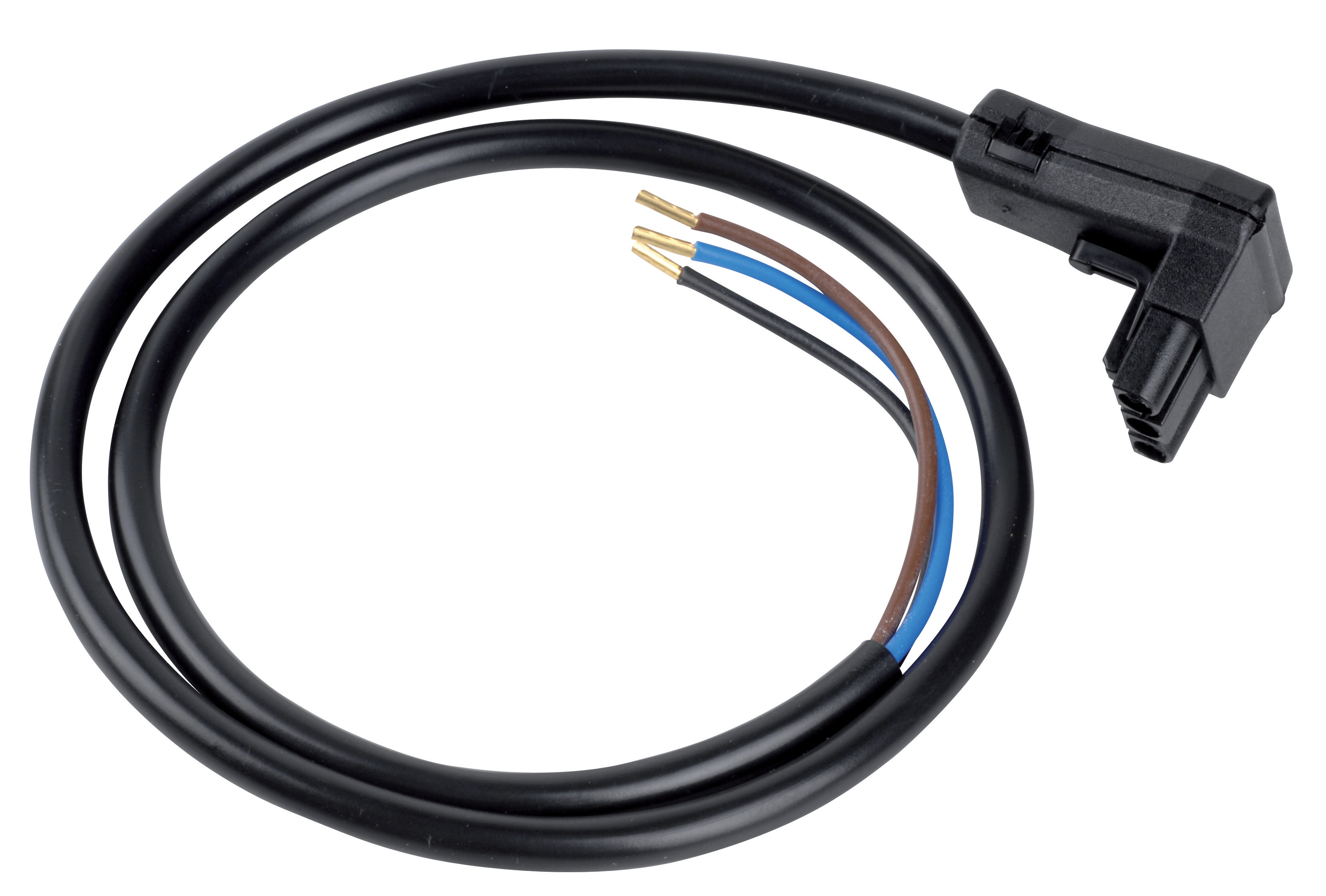
The Satronic IRD 810/820 infrared detector cable is a 4-pole connector specifically engineered for burner control applications. This cable bridges the detector head to the control relay, transmitting the analog flame signal while maintaining signal integrity across frequency ranges of 15–150 Hz. In Singapore's tropical, high-humidity environment, proper cable routing, connector protection, and periodic inspection are critical to preventing moisture ingress and signal degradation.
Infrared detectors excel in applications where:
- Multiple fuel types are burned (gas, oil, or dual-fuel burners)
- Ambient light levels are unpredictable (outdoor units or mixed indoor/outdoor installations)
- Fast response to flame loss is mandatory (safety shutdown within 1–3 seconds)
- Long-term reliability without electrode degradation is prioritized
When specifying IR-based systems, contractors must verify:
1. Viewing angle and lens clarity – Ensure the detector has unobstructed line-of-sight to the flame root. Fouling, carbon buildup, or misalignment reduces sensitivity and increases false ignition cycles.
2. Spectral filter specifications – Confirm the detector filters out infrared radiation outside the combustion band (e.g., solar radiation, incandescent lighting) to minimize nuisance trips.
3. Response time – Most industrial IR detectors respond within 200–400 ms. Verify this meets your burner's ignition and safety shutdown timing requirements.
Signal Conditioning and Control Relay Integration
Flame detection signals are analog, low-level voltages (typically 1–5 mV from an IR cell or 1–10 mV from ionization probes). These signals cannot directly control power circuits; they require amplification and conditioning through dedicated control relays.
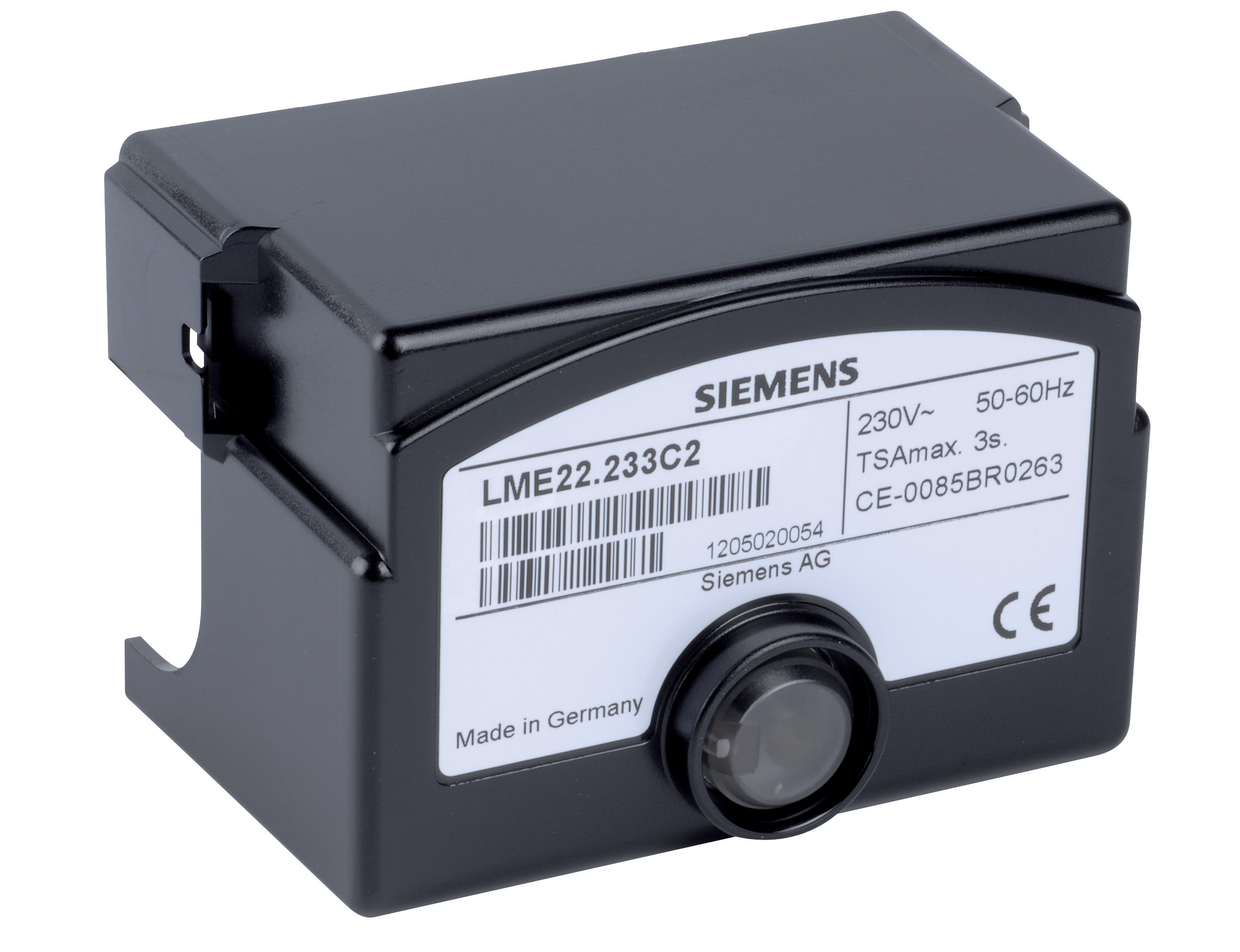
The Satronic Relay DMG 970-N MOD.01 is a burner control relay rated for 50 Hz or 60 Hz operation with 220/240 V or 110/120 V supply. This relay integrates flame detection signal input (compatible with IRD 1020 and UVD 971 flame detectors), processes the signal through internal logic circuitry, and outputs controlled power to gas solenoid valves, ignition transformers, and alarm circuits.
Key integration considerations:
- Input impedance – The relay's flame detector input presents a high impedance load (typically >1 MΩ). This protects the sensitive detector cell from loading effects and maintains signal fidelity.
- Frequency response – The relay's internal signal processing filters and locks onto the flame frequency (typically 25–40 Hz for gas burners, 45–75 Hz for oil burners). Detectors and cables must support this frequency band without phase shift or attenuation.
- Time-delay logic – Commercial relays incorporate adjustable ignition lockout timers (typically 4–8 seconds). This delay prevents nuisance shutdowns from transient flame signals during ignition and allows the burner to reach stable combustion.
- Flame signal failure detection – If the detector signal drops below threshold (indicating flame loss), the relay initiates safety shutdown within 1–3 seconds, cutting power to the gas solenoid valve and stopping fuel supply.
Fast Solenoid Valve Response and Safety Shutdown Architecture
The flame detection relay output controls fast-acting solenoid valves that manage fuel cutoff. Speed and reliability of this valve response are directly tied to system safety.
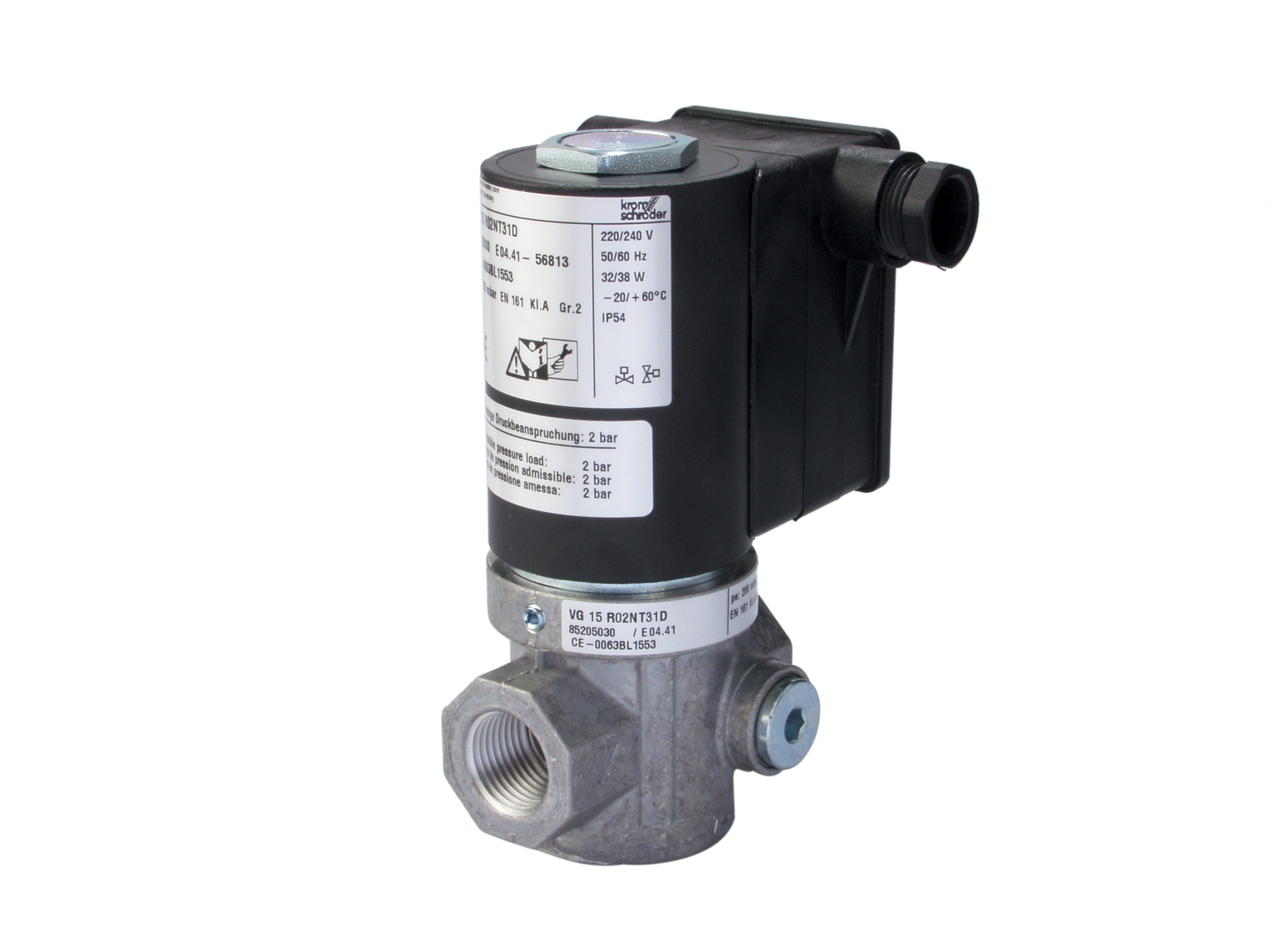
The Kromschroder VAS 115R/NQ fast gas solenoid valve features LED blue control indication and is rated for maximum upstream pressure of 500 mbar. The "fast" designation means the solenoid coil de-energizes with minimal delay (typically <100 ms), allowing internal spring pressure to slam the valve shut within 200–300 ms of command signal loss.
Integration best practices:
1. Coil voltage matching – Verify the solenoid coil operates at the same voltage as the control relay output (e.g., 230 Vac). Use intermediate relays if voltages differ.
2. Electrical noise suppression – Fast solenoid coils generate high-frequency electrical transients during de-energization. Install varistors or diode suppression circuits across the coil to prevent control relay damage.
3. Pressure rating verification – Confirm the valve's rated upstream pressure exceeds your burner's maximum supply pressure by at least 20 %. In Singapore, natural gas supply pressure is typically 30–50 mbar gauge; LPG systems may run 500–2000 mbar depending on regulator setting.
4. Manual shutoff integration – Always install a manual isolation ball valve upstream of the solenoid. This allows safe maintenance of the burner without de-pressurizing the entire fuel line.
5. Flow rate matching – Select the solenoid valve's flow rating to match your burner's fuel consumption. Undersized valves create pressure drop that starves the burner; oversized valves waste energy and increase response time.
Ignition System Architecture and Flame Signal Stability
Ignition and flame detection are interdependent. Poor ignition design creates unstable flame signals that confuse detectors and trigger nuisance shutdowns.
The Sit Control Box Sit 0579311 (replacing 0577311) is a burner control box that manages ignition timing, spark gap management, and flame monitoring in industrial heating systems. It operates at 230 Vac with 25 Hz repetition rate and specifies a 2–4 mm spark gap for reliable ignition. The IP40 protection rating ensures the electronics survive dust and minor splash in typical burner room environments.
Critical ignition-to-flame-detection interaction points:
- Ignition lockout timing – The control relay must disable the flame detection circuit during the ignition period (typically 4–6 seconds). This prevents the ignition spark or pilot light from triggering false flame detection. Most modern relays integrate this logic automatically, but verify in commissioning.
- Spark electrode gap – A 2–4 mm gap produces a high-voltage discharge (typically 6–10 kV) sufficient to ignite fuel-air mixture. Larger gaps (>5 mm) cause weak sparks that fail to ignite consistently; smaller gaps (<2 mm) create excessive current draw and shorten electrode life. Check electrode erosion every 500 operating hours in high-use applications.
- Ignition transformer isolation – The ignition transformer output must be electrically isolated from the flame detection circuit. Leakage from the high-voltage secondary into the detector cable causes false flame signals. Shield all ignition leads away from detector cables, use separate cable trays, and verify 150 mm minimum separation.
Commissioning and Flame Signal Verification Protocol
Proper commissioning is where most field problems surface. A systematic approach prevents months of nuisance shutdowns post-handover.
Step 1: Visual and mechanical inspection
- Confirm the flame detector is mounted with unobstructed line-of-sight to the flame root (typically 30–60 degrees off burner centerline, 100–300 mm distance).
- Check that detector lens is clean and free of thermal stress cracks. In high-temperature applications, allow detectors to cool to ambient before wiping the lens.
- Verify the detector cable is routed away from ignition leads, power wiring, and high-temperature surfaces. Use ceramic or stainless clips; avoid plastic ties near heat sources.
- Confirm solenoid valve is installed upstream of the burner air/fuel mixing chamber with manual isolation and check valve (if required by fuel type).
- Measure supply voltage to the control relay: should be within ±10 % of nameplate rating (e.g., 207–253 Vac for 230 V rated unit).
- With burner off, measure resistance of the flame detector circuit (typically 100–500 kΩ for IR detectors, 0.5–2 MΩ for ionization). Infinite resistance indicates an open circuit (broken cable or detector failure); <100 kΩ indicates moisture ingress or detector degradation.
- Verify the detector output signal frequency matches relay input specification (typically 25–75 Hz with flame present, zero Hz with flame absent).
- Start the burner and allow 5–10 seconds for flame stabilization.
- Observe the control relay's flame detection indicator light (LEDs on most modern relays).
- Use a temporary flame loss test: briefly shield the detector from flame view (do not extinguish the flame). The relay should initiate safety shutdown within 2–3 seconds, and the solenoid valve should cut fuel supply.
- Repeat the test 3–5 times to confirm consistent response. If response varies, the detector signal is marginal; clean the lens or reposition the detector.
- Using a digital oscilloscope and current probe on the solenoid valve coil, trigger a flame loss condition and measure the time from signal drop to solenoid de-energization.
- Typical response: <500 ms from relay command to valve closure (relay logic delay ~50–100 ms + solenoid response ~200–300 ms + mechanical valve slamming ~100–150 ms).
- If response exceeds 800 ms, investigate: aging relay, failing solenoid coil, excessive valve pressure drop, or marginal detector signal.
Common Field Failure Modes and Troubleshooting
Symptom: Frequent nuisance shutdowns during normal operation
Likely causes: Detector lens fouling, detector misalignment, cable moisture ingress, electromagnetic interference (EMI) from nearby VFDs or welding equipment, or relay sensitivity drift.
Solution: Clean detector lens; verify 300 mm minimum clearance from high-current power cables; check cable insulation resistance; replace the relay if all mechanical checks pass.
Symptom: Burner fails to light; relay shows no flame detection
Likely causes: Ignition failure (no spark), detector pointing away from flame, detector failure, or broken cable.
Solution: Verify ignition produces visible spark at electrode gap; confirm flame detector LED or indicator activates when burner is lit; measure detector output voltage (should be >0.5 V with flame, 0 V without); replace cable if resistance is infinite.
Symptom: Delayed response to flame loss (>3 seconds)
Likely causes: Relay lockout timer not configured for your fuel type, aging relay contacts, or solenoid valve stiction.
Solution: Check relay lockout timer setting (should be <4 seconds); manually cycle solenoid valve coil 20–30 times to free internal spool; consider solenoid valve replacement if cycling does not restore fast response.
Symptom: Burner cycles on and off erratically
Likely causes: Air/fuel ratio unstable (burner control valve hunting), flame signal marginal (detector nearly threshold), or relay sensitivity drift.
Solution: Verify air/fuel ratio control is stable with manometer or flue gas analyzer; increase detector sensitivity (if adjustable) or reposition closer to flame; verify relay input signal amplitude is >2 V peak (well above threshold).
Maintenance and Lifecycle Management
Flame detection systems require periodic maintenance to maintain safety and reliability.
Annual maintenance:
- Visual inspection of detector lens; clean with soft, dry cloth or compressed air if fouled.
- Measure flame detector resistance; trending data reveals aging detectors before failure.
- Verify relay supply voltage is within tolerance; measure flame detection output signal with burner running.
- Inspect solenoid valve for external corrosion or oil seepage; manually cycle coil 10–15 times to confirm fast response.
- Replace detector cable if physical damage, moisture, or corrosion is evident.
- Consider relay replacement if nuisance shutdowns increase despite field maintenance (suggests internal wear).
- Verify ignition electrode spacing and replace if erosion reduces gap below 2 mm.
- Maintain a commissioning record: detector model, cable part number, solenoid valve rating, relay response time baseline, and baseline detector resistance/signal amplitude.
- Record all service visits: cleaned lens, replaced cable, relay response time after service.
- Trending this data allows predictive maintenance; a 50 % increase in relay response time signals impending failure.
Singapore-Specific Considerations
Singapore's tropical climate and dense industrial environment create unique challenges:
- High humidity and salt spray – Coastal facilities experience accelerated corrosion of ignition electrodes and solenoid valve spools. Schedule maintenance every 6 months in coastal industrial areas.
- Electromagnetic interference (EMI) – Dense urban industrial zones with multiple burners, VFDs, and wireless communication systems generate significant EMI. Use shielded, twisted-pair detector cables and keep cable runs >300 mm from power conduits.
- Power supply variability – Some Singapore facilities experience voltage transients during peak demand periods. Verify relay supply voltage stability with a true RMS meter over a 24-hour period. Install voltage suppression at the main disconnect if swings exceed ±10 %.
- Spare parts availability – 3G Electric stocks the major control relays (Satronic DMG 970-N MOD.01, Sit 0579311), fast solenoid valves (Kromschroder VAS 115R/NQ), and detector cables (Satronic IRD 810/820) used in Singapore's HVAC infrastructure. Maintain spares on-site for critical burner installations to minimize downtime during field failures.
Best Practices Summary
Reliable flame detection depends on five fundamentals:
1. Correct sensor selection – Match infrared or ionization detection to your fuel type and burner geometry.
2. Proper installation – Position detectors for unobstructed flame view; route cables away from ignition and power leads.
3. Signal integrity – Verify detector output signal frequency, amplitude, and response time during commissioning.
4. Control relay coordination – Confirm relay lockout timers, sensitivity, and flame loss response match system requirements.
5. Preventive maintenance – Clean detector lenses, check cable insulation, and trend detector resistance annually.
By mastering these principles and leveraging 35+ years of industrial equipment experience, HVAC contractors in Singapore can deliver burner systems that operate safely, reliably, and with minimal nuisance shutdowns.