Controls & Safety: Emergency Shutdown and Lockout-Tagout Integration
Emergency shutdown procedures and lockout-tagout (LOTO) systems form the foundation of safe industrial burner operations. In Southeast Asia's rapidly expanding industrial sector, understanding how to properly integrate emergency controls with safety relay architectures is essential for protecting personnel and equipment. With over 35 years of experience distributing industrial controls, 3G Electric has observed that many facilities lack comprehensive emergency shutdown protocols—a gap that can have serious consequences.
Proper Controls & Safety implementation requires more than component selection; it demands a systematic approach to emergency response. This article focuses on practical emergency shutdown design, LOTO integration points, and verification procedures that industrial professionals in Southeast Asia need to implement.
Understanding Emergency Shutdown Architecture
Emergency shutdown systems operate independently from normal burner control sequences. They must function reliably even when primary control systems fail, which is why redundancy and fail-safe design principles are paramount.
Emergency stops (E-stops) must be hardwired directly to safety relays, not controlled through programmable logic. The Kromschroder Relay BCU 570WC1F1U0K1-E provides the kind of safety-rated control architecture needed for this application. This relay supports both direct and piloted ignition modes while maintaining EN 746-2 and EN 676 compliance—standards that explicitly require emergency shutdown capability.
Key architectural considerations include:
- Hardwired E-stop circuits operating at voltage levels that de-energize solenoid valves immediately
- Dual-channel monitoring where possible, ensuring that a single component failure cannot prevent shutdown
- Manual reset requirements that prevent automatic restart after emergency activation
- Visual confirmation through indicator lights and status displays
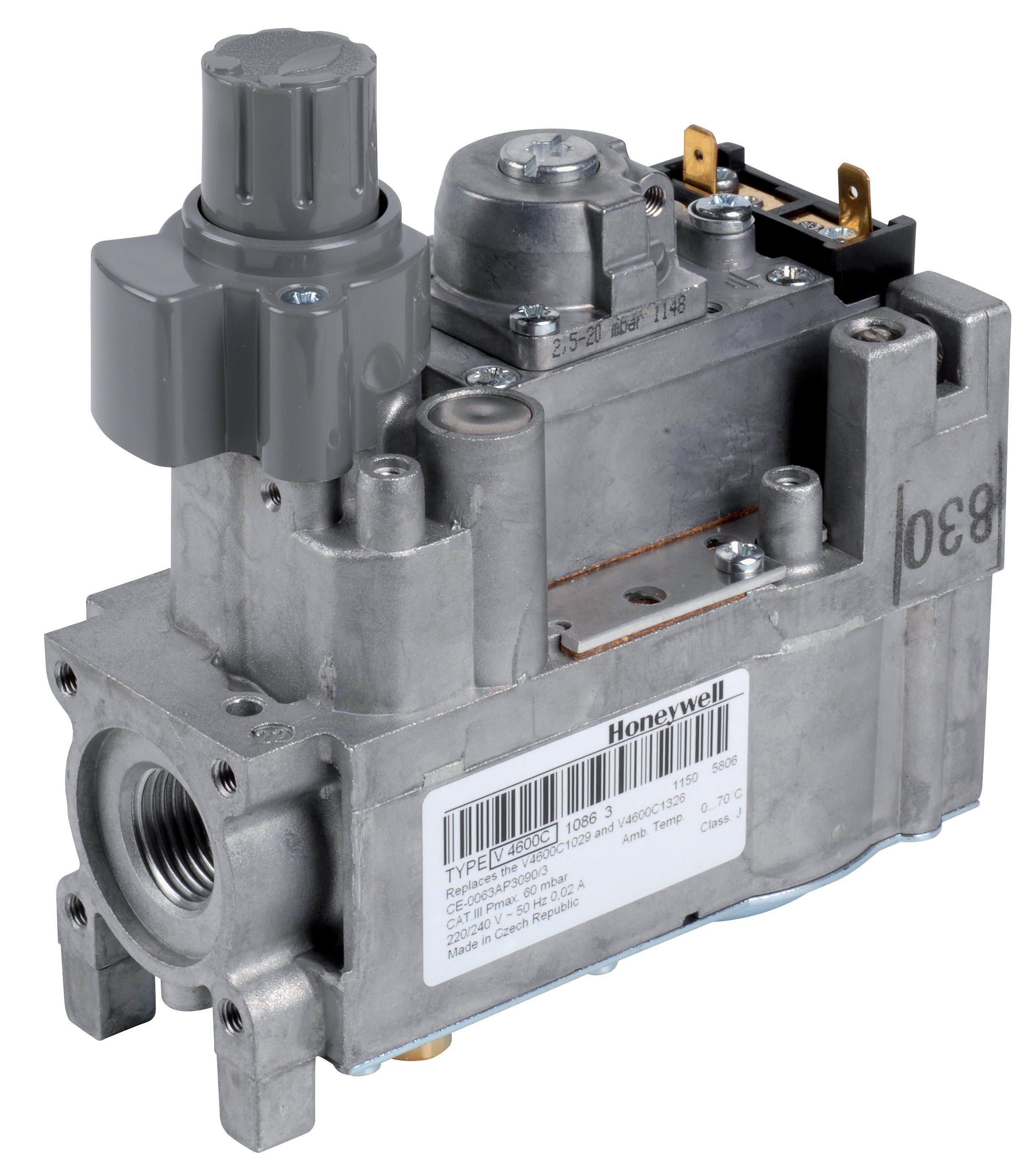
When an E-stop button is activated, the signal must interrupt the coil voltage of gas block solenoids instantaneously. The Honeywell Gas block VK 4105 C 1041 U is designed with modulating capability, but its electrical supply must be interrupted by emergency circuits regardless of control signal intent.
Integrating LOTO Procedures with Control Systems
Lockout-tagout procedures prevent energization of equipment during maintenance or repair. In burner control systems, LOTO integration must address multiple energy sources: electrical, gas pressure, and thermal energy.
Electrical Energy Control Points:
The primary LOTO point is the main disconnect serving the control system. All safety relays—including the Siemens Relay LFL 1.622 for burner monitoring—must de-energize when this disconnect is opened. However, LOTO procedures must also consider:
- Solenoid valve coils that may retain residual voltage
- Flame monitoring circuits that may store energy in capacitors
- Ignition transformer secondary circuits on the Pactrol Housing P 16 DI CE which can discharge hazardous voltage
Proper LOTO requires verifying zero voltage at all control terminals before maintenance begins. This verification step prevents accidental energization during work.
Gas Energy Control Points:
Gas energy must be isolated using block valves upstream of the burner fuel supply. LOTO procedures should specify:
- Closing manual block valves and tagging them
- Allowing pressure to bleed from solenoid valve pilot lines
- Opening vent ports to atmosphere to eliminate trapped pressure
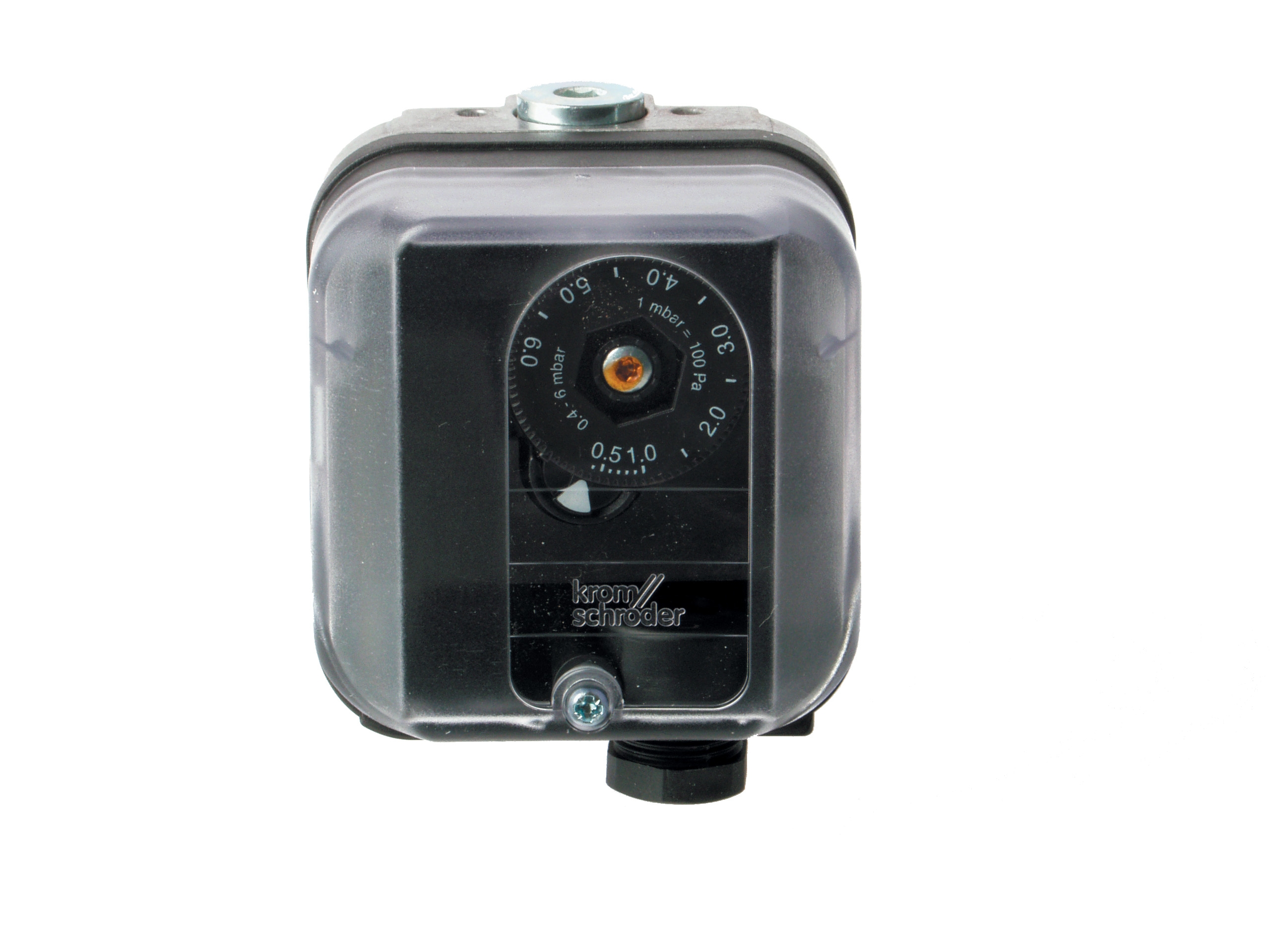
The Kromschroder Pressure switch DG 50U/6, rated SIL 3, provides pressure monitoring that should be visible during LOTO verification. Technicians can confirm pressure has been eliminated by observing the pressure switch status—it should remain de-energized after gas isolation.
Thermal Energy Control:
Burner systems retain heat after shutdown. LOTO procedures must include cooling verification before maintenance begins. Temperature monitoring—either through thermostats or direct measurement—ensures the burner chamber has reached safe handling temperature.
Designing E-Stop Button Placement and Response Networks
Emergency stop button placement significantly affects response time and personnel safety. In Southeast Asian facilities with high humidity and corrosive salt-air environments (particularly in coastal regions), E-stop button enclosures must be rated for IP65 or higher.
Spatial Placement Strategy:
- Install E-stops at operator stations and at primary access points to the burner area
- Position buttons at heights between 0.6 and 1.7 meters for accessibility
- Use distinctive red buttons with yellow backgrounds per ISO 13850
- Ensure minimum 10-meter cable runs to prevent signal delay
E-stop circuits should be configured in series—each button connects in parallel with other buttons, but all series together in the shutdown path. This means any activated button triggers shutdown regardless of button state. Safety relays like the Kromschroder BCU 570WC1F1U0K1-E must immediately de-energize their output contacts when E-stop signal is received.
Response time from button activation to fuel cutoff should not exceed 200 milliseconds. Verify this timing during commissioning and periodically during maintenance cycles.
Testing, Verification, and Documentation Requirements
Emergency shutdown and LOTO systems must be tested regularly. Southeast Asian regulatory frameworks increasingly require documented evidence of these tests.
Functional Testing Schedule:
- Weekly: Manual E-stop button activation with visual confirmation of fuel solenoid de-energization
- Monthly: Full shutdown sequence with manual fuel valve isolation
- Quarterly: Multi-point E-stop testing (if multiple buttons exist)
- Annually: Professional load testing of safety relay response circuits
Maintain records showing:
- Test dates and results
- Technician names and certifications
- Any anomalies or delayed responses
- Component replacement dates
- Pressure switch response verification (confirming the Kromschroder DG 50U/6 properly detects shutdown)
Photographic documentation of LOTO points—showing valve positions, disconnect handles, and tagged equipment—provides evidence of proper procedure implementation.
Southeast Asia-Specific Considerations
Southeast Asian industrial operations face unique environmental and operational challenges:
Tropical Humidity and Corrosion:
Salt-air environments in coastal areas accelerate corrosion of E-stop button contacts and relay terminals. Use stainless steel enclosures and apply conformal coating to control circuit boards. The Pactrol Housing P 16 DI CE with proper IP rating provides protection, but regular inspection of external connections is essential.
Electrical Supply Variability:
Voltage fluctuations are common in some Southeast Asian regions. Safety relays must maintain function across ±10% supply voltage variation. Specify relays with input voltage range documentation and verify during commissioning.
Multilingual Workforce:
E-stop labels and LOTO procedure signs should be in local languages plus English. Use pictorial symbols (per ISO 1219) that are understood across language barriers.
Extended Maintenance Intervals:
Some facilities operate in remote locations where technician visits occur infrequently. Design systems that allow operators to verify controls status independently. Pressure switches like the Kromschroder unit provide visual feedback that requires no instrumentation.
Common Implementation Errors and How to Avoid Them
Error 1: E-stop circuits controlled through programmable logic
- Solution: E-stops must be hardwired to safety relay inputs, bypassing any programmable control
- Solution: Specify temperature thresholds (e.g., below 50°C) before maintenance begins
- Solution: Combine pressure indication with manual flame verification and fuel valve status checks
- Solution: Require manual intervention after any E-stop activation; automation should not restart
- Solution: Run E-stop wiring in separate conduit from power circuits to prevent cross-talk
Practical Implementation Checklist
Use this checklist when designing or upgrading emergency shutdown and LOTO systems:
- [ ] E-stop buttons installed at all operator and maintenance access points
- [ ] Hardwired shutdown circuits independent from programmable controls
- [ ] Solenoid valves (like those controlled via the Honeywell VK 4105 unit) verified to de-energize within 200ms
- [ ] Pressure isolation points identified and labeled in facility documentation
- [ ] LOTO procedure documentation in local language(s)
- [ ] Monthly functional testing schedule established with documentation system
- [ ] Annual third-party verification of safety relay response (Kromschroder BCU 570WC1F1U0K1-E and Siemens LFL 1.622)
- [ ] E-stop enclosure IP rating appropriate for facility environment (IP65+ for humid/salt-air areas)
- [ ] Emergency lighting and signage installed
- [ ] Personnel training completed for all operators and maintenance technicians
Conclusion
Controls & Safety systems protect both personnel and equipment in industrial burner operations. Emergency shutdown and LOTO integration represents the outer ring of the safety architecture—the last line of defense when normal controls fail. Southeast Asian industrial professionals must implement these systems with the same rigor applied to pressure monitoring and flame detection.
3G Electric's 35+ years experience distributing industrial controls demonstrates that emergency systems are most effective when integrated into overall facility design rather than added as afterthoughts. Specify safety-rated components from the beginning, design redundancy into critical circuits, and establish regular testing protocols that build confidence in system reliability.
The components referenced—from the Kromschroder pressure switches that enable shutdown verification to the safety relays that execute shutdown commands—work together as a system. Proper integration of these components with well-designed emergency procedures creates the layered protection Southeast Asian industrial operations require.