Understanding Controls & Safety in Crisis Situations
Controls & Safety systems are your plant's first line of defense against catastrophic failures. Yet most plant managers receive minimal training on what to do when these systems malfunction. With over 35 years of experience supporting industrial operations across Southeast Asia, 3G Electric has seen how quickly a simple control failure can cascade into operational shutdown, safety incidents, or regulatory violations.
This guide differs from typical installation manuals. Instead, it focuses on the practical decisions you'll make when your burner control system fails at 2 AM on a Sunday, when your safety relay won't reset, or when flame detection becomes unreliable during critical production cycles.
Section 1: Immediate Diagnosis and Triage Protocols
The First 60 Seconds: What You Need to Know
When a Controls & Safety failure occurs, your response in the first minute determines whether you'll recover in hours or days. Here's what plant managers must do immediately:
Step 1: Confirm the Actual Failure
Don't assume the entire control system failed. Eighty percent of "control failures" are actually gas supply issues, blocked fuel filters, or tripped solenoid valves. Before calling your supplier:
- Verify fuel pressure at the main inlet
- Check that the manual isolation valve is fully open
- Listen for solenoid click sounds (indicating electrical signal is reaching the valve)
- Confirm pilot light visibility if your system uses pilot ignition
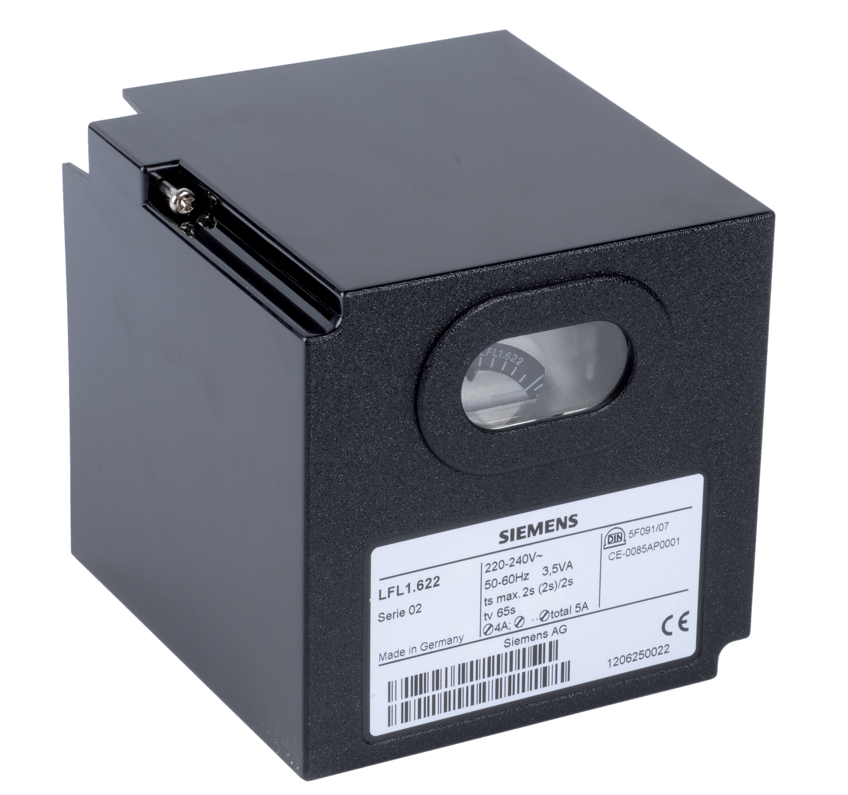
Modern burner control systems use modular components. Knowing which module failed prevents unnecessary replacement of the entire assembly. The Kromschroder BCU 570WC1F1U0K1-E relay, for example, handles ignition and pilot monitoring separately. If only pilot flame detection fails, you're replacing one module, not the entire relay.
Use this diagnostic sequence:
1. Ignition System: Does the igniter spark? If yes, ignition module is functional. If no, check 120V supply to igniter transformer.
2. Flame Detection: Does the flame detection circuit respond when you manually introduce a flame to the flame sensor? If yes, the sensor works; the problem is upstream in the flame monitoring relay.
3. Safety Shutoff: Can you manually reset the system? If the reset button is non-responsive, the solenoid valve or its control relay has failed.
Component-Specific Failure Modes
Burner Control Relays (such as the Brahma Relay CM 31 F TW10/TS5):
- Most common failure: Loss of intermittent pilot flame during startup
- Diagnosis: Check for 24V power at the relay terminals
- Recovery: Reset sequence typically requires 30-second power-off period
- Prevention: These relays are sensitive to voltage fluctuations; ensure your UPS-backed 24V supply is stable
- Most common failure: Sticking contacts after 5+ years of operation
- Diagnosis: Tap the switch gently with a wrench while monitoring circuit continuity
- Recovery: If tapping temporarily restores function, the switch needs replacement within 7 days
- Prevention: Schedule replacement every 5 years in high-vibration environments
- Most common failure: Thermoelectric pilot valve weakening over time
- Diagnosis: Does the manual safety button require increasing force to hold down?
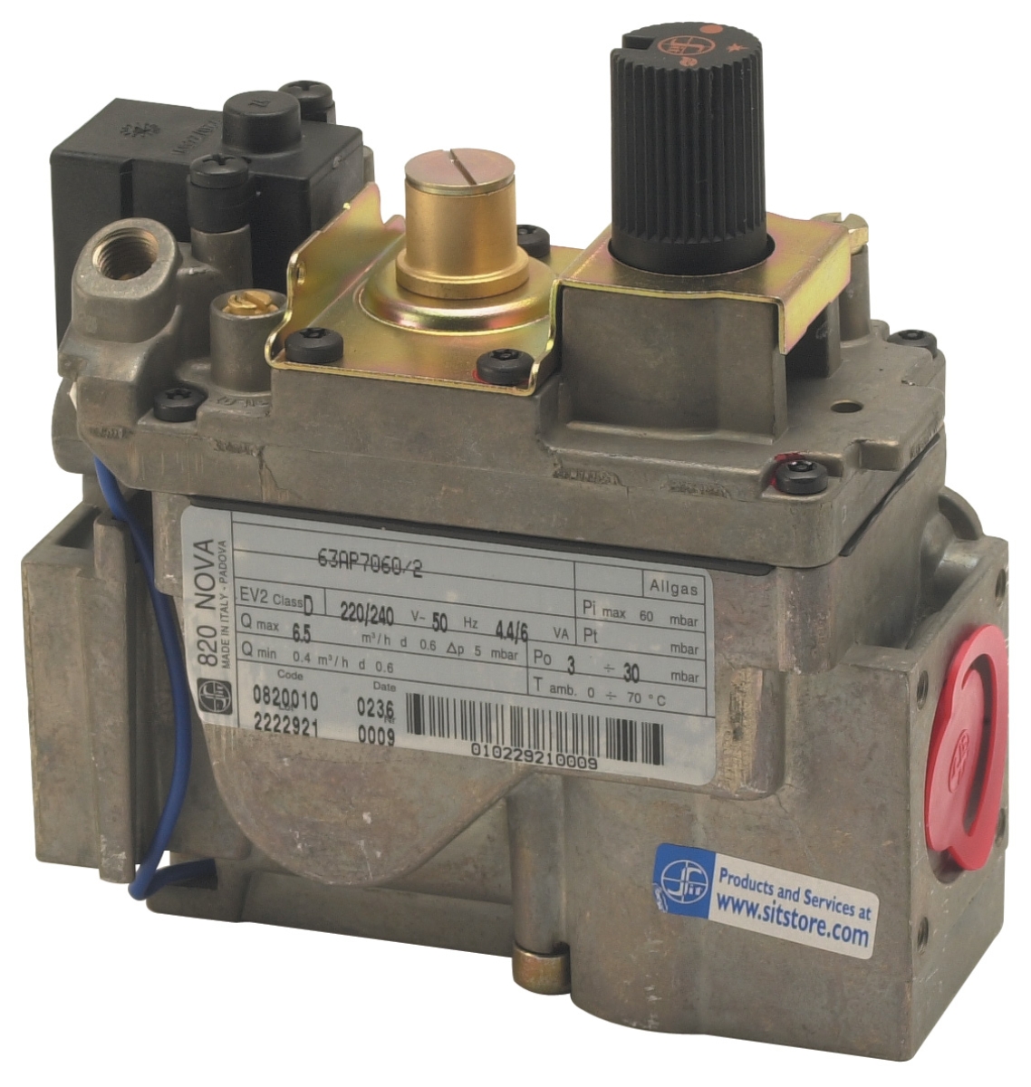
- Recovery: Multifunctional blocks rarely fail completely; pilot flame monitoring usually fails first
- Prevention: These blocks are non-repairable; keep one in stock as a hot-swap replacement
- Most common failure: UV flame detection lens fouling in dusty environments
- Diagnosis: Clean the UV sensor window with a soft cloth; if sensitivity returns, it was fouling
- Recovery: If sensitivity doesn't return after cleaning, internal sensor has failed
- Prevention: In dusty plants, inspect UV sensors monthly
Section 2: Emergency Recovery Procedures
The Safe Shutdown Protocol
When controls fail, resist the urge to force-restart. Instead:
1. Isolate the fuel supply: Close the manual block valve immediately
2. Wait 60 seconds: Allows gas in the combustion chamber to clear
3. Power cycle the entire control system: Turn off main power switch, wait 30 seconds, restore power
4. Attempt one restart sequence: If this fails, move to manual diagnostic mode
Manual Diagnostic Mode (Non-Production Restart)
This procedure lets you identify which component failed without risking personnel or equipment:
1. Verify 24V power supply: Use a multimeter at the main control relay terminals. You should see 23.5-24.5V DC. Anything outside this range indicates a power supply issue—contact your electrical contractor.
2. Test ignition module: With power on, measure voltage at the igniter terminals. You should see 0V normally, then 120V+ when you press the ignition test button (usually built into the relay or accessible via test leads). If no voltage, the ignition module is failed.
3. Test flame detection circuit: Once you have confirmed ignition works, manually introduce a flame to the flame sensor (hold a lighter below the sensor). The control relay should change state. If it doesn't respond, the flame detection module is failed.
4. Test safety shutoff solenoid: With 24V power confirmed, verify that the solenoid valve clicks when the reset button is held. If no clicking sound, check for 24V at the solenoid terminals. No voltage means relay failure; voltage present but no click means solenoid failure.
When to Call Your Distributor
Contact 3G Electric or your local distributor immediately if:
- You have confirmed 24V power but the relay/solenoid shows no response
- You detect a burning smell from the control relay
- The flame detection circuit fails immediately after replacement
- Any component generates excessive heat (more than hand-temperature)
Section 3: Preventive Strategies to Minimize Emergency Situations
Quarterly Maintenance Schedule for Southeast Asian Plants
Southeast Asia's tropical climate—high humidity, salt air in coastal areas, and seasonal monsoon conditions—accelerates control component degradation. A quarterly maintenance routine prevents 85% of emergency failures:
Month 1 (Every 3 months)
- Inspect relay housing for corrosion or moisture
- Clean flame detection sensor with soft, lint-free cloth
- Verify 24V supply voltage and stability
- Test emergency shutdown function (manual reset button)
- Replace 24V power supply filter (if equipped)
- Inspect solenoid valve manual override for sticking
- Measure fuel pressure at control block inlet—should match nameplate specs
- Check all electrical connectors for green corrosion
- Perform complete restart sequence under load; note time to stable flame
- Inspect pressure switch calibration (consult original equipment manual)
- Verify that safety relay reset mechanism functions smoothly
- Document any unusual clicking, buzzing, or humming sounds
Component Replacement Strategy
Keeping critical components in stock prevents multi-day downtime. For Southeast Asian operations with production demands, maintain:
- One spare safety relay matching your primary system (cost: $400-800)
- One spare gas control block (cost: $150-400)
- Two spare pressure switches (cost: $200-400)
These three items address 75% of emergency failures. Store them in sealed plastic cases with silica gel packets to prevent humidity damage.
Regional Compliance Considerations
Singapore's PUB (Public Utilities Board) standards require documented maintenance logs for all gas-fired equipment. Malaysia's DOSH (Department of Occupational Safety and Health) mandates safety system testing every 6 months. Thailand and Vietnam enforce similar requirements through local fire safety authorities.
Maintain a simple log documenting:
- Date of maintenance
- Components inspected or replaced
- Test results (especially emergency shutdown response time)
- Any anomalies detected
This documentation protects you during regulatory audits and helps your distributor provide faster support when failures occur.
Section 4: Advanced Troubleshooting for Persistent Problems
Intermittent Failures: The Most Dangerous Scenario
A control that fails randomly, then restarts on its own, is more dangerous than a complete failure because it masks the underlying problem. Common causes:
1. Loose electrical connections: Check all 24V supply connections. Corrosion under connector terminals is invisible until you remove the connector and inspect.
2. Voltage sag during ignition: Some plants experience 18V-20V dips when the igniter fires, which is insufficient for safe relay operation. Solution: Upgrade to a larger 24V UPS or dedicated power supply for control circuits.
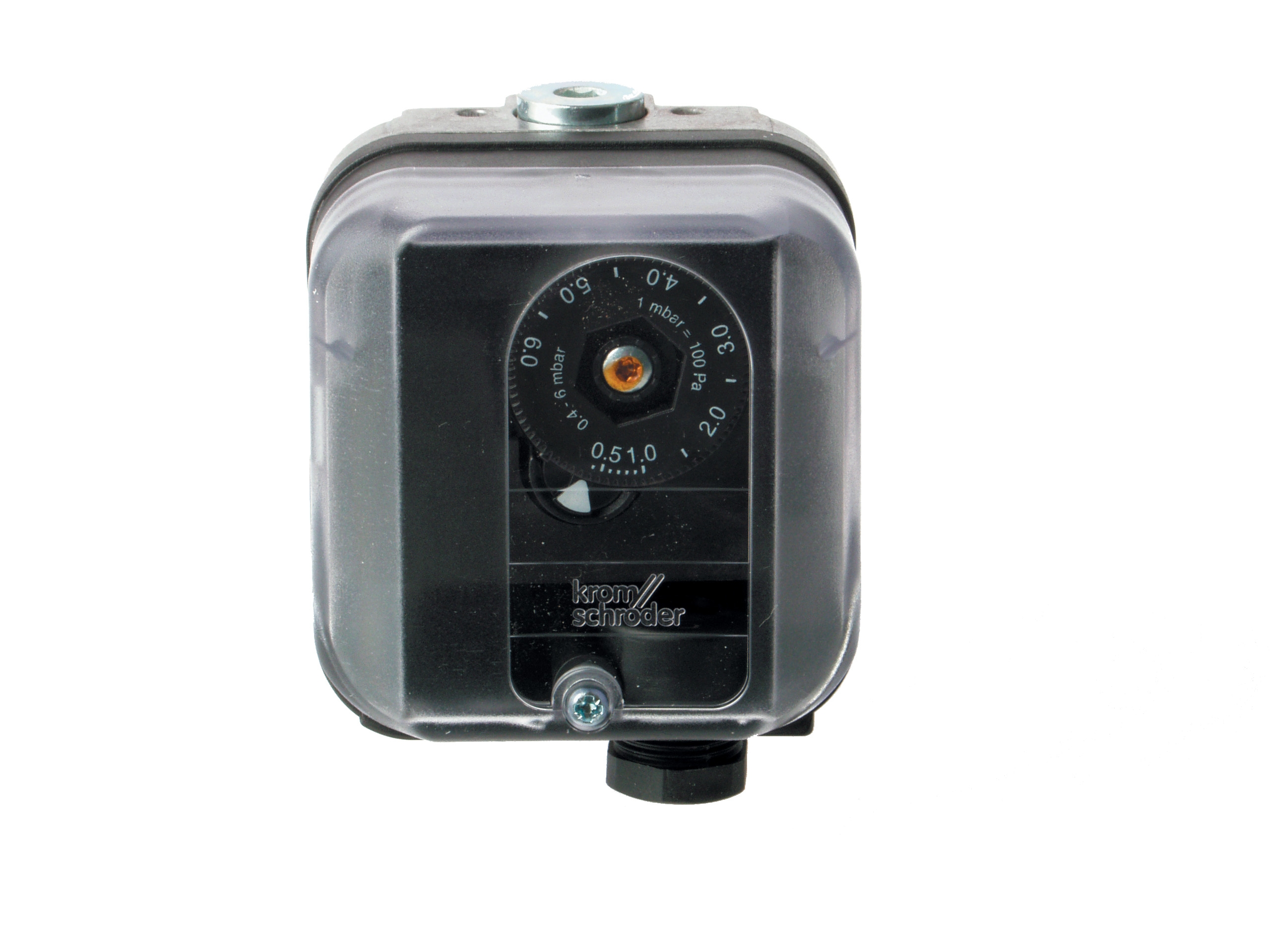
3. Fuel supply fluctuation: If pressure varies ±0.5 bar during operation, the pressure switch may chatter. The Kromschroder DG 50U/6 pressure switch is rated SIL 3 and won't malfunction, but it indicates upstream gas supply problems—check for partially closed block valves or debris in fuel lines.
4. Temperature sensitivity: In regions where ambient temperature swings 20°C daily, control relays can drift out of specification. If failures cluster around 2-3 AM (coolest part of day), suspect temperature drift—relocate controls away from external walls or add thermal insulation.
Documentation You'll Need for Faster Support
When contacting 3G Electric for emergency support, have ready:
- Model and serial numbers of your burner and control system
- Last maintenance date and what was done
- Ambient temperature when failure occurred
- Fuel pressure reading at time of failure (if you can safely measure it)
- Voltage reading at control relay terminals
- Error codes or indicator light patterns (if your system displays them)
With 35+ years supporting Southeast Asian industrial plants, our technical team can often diagnose issues remotely with this information, potentially saving you 2-4 hours of troubleshooting.
Conclusion: Building Resilience Into Your Operations
Controls & Safety failures are inevitable in industrial operations. The difference between a 30-minute incident and a 48-hour catastrophe is preparation. By understanding failure modes, maintaining quarterly documentation, and stocking critical spare components, you transform uncontrollable crises into managed incidents.
Southeast Asian industrial conditions—salt air, humidity, temperature swings, and variable power quality—demand more aggressive maintenance than textbook recommendations suggest. The protocols in this guide are calibrated for these specific regional challenges based on thousands of installations across Singapore, Malaysia, Thailand, and Vietnam.