Introduction: Understanding Burners & Combustion System Integration
Burners & Combustion systems represent one of the most critical components in industrial heating infrastructure, yet their integration and optimization remain poorly understood across many facilities. For over 35 years, 3G Electric has supplied industrial heating equipment globally, and we've observed that most combustion efficiency problems stem not from equipment defects, but from improper system integration and tuning.
Proper burner and combustion system integration requires understanding how mechanical components, control logic, and fuel delivery work in concert. This guide provides industrial professionals with actionable procedures for evaluating system architecture, calculating optimal operating parameters, and implementing controls that deliver consistent, efficient combustion across varying load conditions.
Whether you're commissioning a new installation, troubleshooting underperformance, or upgrading legacy systems, understanding system-level integration principles will improve operational efficiency and extend equipment lifespan.
Section 1: Fundamentals of Burner System Architecture and Control Integration
Core System Components and Their Relationships
Industrial burner systems consist of five integrated subsystems: fuel supply, air supply, ignition and flame monitoring, burner mechanics, and control logic. Each subsystem influences the others, making isolated component analysis insufficient for optimizing combustion performance.
Fuel Supply Subsystem: This includes fuel storage, pumps, pressure regulation, solenoid valves, and atomization equipment. Pressure stability directly affects droplet size distribution in oil burners and injection timing in gas systems. Unstable fuel pressure causes combustion instability and increased emissions.
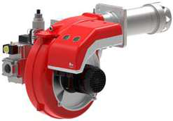
Air Supply Subsystem: Forced-draft or natural-draft air delivery must be balanced with fuel flow to maintain stoichiometric or slightly oxidizing conditions. Air dampers, forced-draft fans, and intake filtration all influence oxygen availability at the combustion zone. The FBR GAS XP 60/2 CE TC EVO incorporates integrated air management for consistent two-stage operation across 116–630 kW thermal power.
Ignition and Flame Monitoring: Modern systems employ ultraviolet (UV) flame sensors or ionization detection coupled with safety control relays. The Siemens LFL 1.622 safety control unit monitors flame presence using both UV and ionization detection, supporting continuous and intermittent pilot ignition modes for gas, oil, and dual-fuel burners.
Burner Mechanics: The physical burner head, nozzle design, swirl air registers, and combustion chamber geometry determine flame stability and burn pattern. Different burner types require different control strategies—single-stage burners operate at fixed output, while modulating burners vary output continuously.
Control Logic: The orchestration of all subsystems occurs through control relays and programmable controllers. The Kromschroder BCU 570WC1F1U0K1-E relay manages direct ignition and pilot ignition sequences while monitoring safety interlocks per EN 746-2 and EN 676 standards.
Integrated System Commissioning Philosophy
Proper commissioning follows a sequential protocol:
1. Mechanical verification: Confirm all fuel lines, air intake, combustion chamber, and drain lines are installed per design specification.
2. Pressure and flow testing: Verify fuel pressure at the burner inlet without ignition active.
3. Air damper calibration: Set air intake dampers to manufacturer baseline position.
4. Safety system validation: Confirm flame sensing, pressure switches, and control relay responses.
5. Ignition sequence testing: Execute ignition cycles without fuel to verify electrode performance.
6. Fuel ignition and flame establishment: Introduce fuel and establish stable flame.
7. Fuel-air ratio optimization: Adjust air dampers and fuel pressure to achieve target combustion efficiency.
8. Load modulation testing: If applicable, verify burner response across the operating range.
This systematic approach prevents the common mistake of adjusting burner output without first establishing proper system baseline conditions.
Section 2: Fuel-Air Ratio Optimization and Combustion Efficiency
Understanding Stoichiometric Balance
Combustion efficiency depends fundamentally on fuel-air ratio—the mass ratio of air to fuel supplied to the combustion zone. The stoichiometric ratio represents the theoretical air quantity required for complete combustion of fuel.
- Natural gas (methane): Stoichiometric air requirement is approximately 17.2:1 by mass
- Light fuel oil (No. 2 diesel): Stoichiometric air requirement is approximately 14.7:1 by mass
- Heavy fuel oil: Stoichiometric air requirement is approximately 14.3:1 by mass
Running slightly fuel-rich (below stoichiometric) produces incomplete combustion, carbon monoxide, and efficiency loss. Running excessively lean (above stoichiometric) increases NOx emissions and risks flame instability. Industrial practice typically targets 3–5% oxygen in flue gas, which corresponds to approximately 15–20% excess air.
Measuring and Adjusting Combustion Quality
Proper optimization requires flue gas analysis equipment: an oxygen meter, carbon monoxide analyzer, and temperature probe. The measurement procedure involves:
1. Establish steady-state operation: Run the burner at the target power level for 10–15 minutes to achieve thermal equilibrium.
2. Insert probe into flue gas stream: Position the probe in the exhaust duct 6–12 inches from the stack exit to avoid temperature extremes.
3. Record oxygen percentage: Target values range from 3% to 6% O₂ depending on fuel type and burner design.
4. Monitor carbon monoxide: CO levels should remain below 100 ppm for natural gas, below 50 ppm for oil burners. Elevated CO indicates incomplete combustion.
5. Adjust air damper incrementally: Make small adjustments (1–2 millimeters) to air intake dampers, waiting 3–5 minutes between adjustments for system response.
Modulating burners require this optimization at multiple load points (typically 30%, 50%, 75%, and 100% output). The FBR KN 1300/M TL EL dual-fuel heavy oil burner operates with modulating control, requiring fuel-air optimization across its full 1700–11500 Mcal/h range.
Using Pressure Switches for Fuel-Air Balance Control
Pressure differential switches monitor the relationship between fuel and air pressures, providing automatic feedback for burner control. The Kromschroder DG 50U/6 pressure switch is rated SIL 3 and meets EN 1854, FM, UL, AGA, and GOST-TR standards, making it suitable for safety-critical applications.
Proper installation involves:
- Mounting the differential pressure switch with +1.5 inch water column sensitivity for air/fuel balance on gas burners
- Connecting high-pressure port to air supply duct
- Connecting low-pressure port to fuel supply line
- Setting switch deadband to allow 0.2–0.3 inch water column hysteresis
This configuration automatically protects against fuel-rich conditions that could cause flame instability or incomplete combustion.
Section 3: Multi-Fuel Systems and Dual-Fuel Commissioning
System Architecture for Gas-Oil Changeover
Dual-fuel systems complicate integration because gas and oil require different atomization strategies, different air register settings, and different ignition approaches. The primary integration challenge involves maintaining consistent combustion performance when switching fuels.
Gas operation requires:
- Lower pressure (typically 3–7 psi) for pressure atomization
- Rapid fuel shutdown (within 0.5 seconds) for safety
- UV flame detection only (ionization unsuitable for gas)
- Higher pressure (typically 100–150 psi) for mechanical or pressure-jet atomization
- Heating of heavy fuel oil to reduce viscosity (for No. 6 fuel)
- Both UV and ionization flame detection
Commissioning Dual-Fuel Systems
1. Establish gas baseline first: Commission the gas-fired operation completely before introducing oil.
2. Document gas parameters: Record optimal fuel pressure, air damper position, oxygen percentage, and flame signal strength.
3. Introduce oil operation: Activate oil solenoid valve while blocking gas supply.
4. Adjust oil-specific parameters: Modify air damper position for oil combustion (typically requires 10–20% more air than gas).
5. Optimize oil fuel pressure: Adjust fuel pressure within the 100–150 psi range to achieve target flame length and heat release.
6. Verify changeover logic: Test automatic switching from gas to oil and manual override controls.
7. Document fuel-specific settings: Maintain separate commissioning logs for each fuel to support future troubleshooting.
The FBR KN 1300/M TL EL illustrates this complexity—as a dual-fuel heavy oil burner, it requires independent tuning protocols for each fuel type to achieve the full 1700–11500 Mcal/h power range.
Managing Transition Between Fuels
Automatic changeover systems require interlocked control logic to prevent simultaneous gas and oil injection. Implementation involves:
1. Purge cycle before switching: Allow 30–60 seconds of air-only operation to clear the previous fuel from the combustion zone.
2. Pressure validation: Confirm fuel supply pressure has stabilized before opening solenoid valves.
3. Ignition reset: Reset safety control relays to initiate fresh ignition sequence for the new fuel.
4. Flame establishment timeout: Allow 3–5 seconds for stable flame before declaring successful changeover.
Safety relays like the Kromschroder BCU 570WC1F1U0K1-E manage these sequences automatically, supporting both direct ignition and intermittent/continuous pilot ignition modes as required by different fuel types.
Section 4: Practical Testing and Validation Procedures
Pre-Commissioning Checklist
Before introducing fuel to the system, verify:
- Electrical connections: All control relay terminals, solenoid valve coils, and ignition transformer connections are secure and rated for local voltage (230V, 400V, 480V, etc.)
- Mechanical integrity: Fuel lines show no cracks, solenoid valve screens are clean, and fuel filter elements are new
- Air pathway: Forced-draft fan rotates freely, intake filter is clean, and combustion air supply shows no blockages
- Safety interlocks: Low fuel pressure alarm, airflow switch, and flame failure shutdown are operational
- Instrumentation: Thermocouples for flue gas temperature, pressure gauges for fuel and air, and oxygen analyzers are calibrated
Ignition System Testing (No-Fuel Sequence)
1. Close all fuel supply valves and confirm burner fuel lines are depressurized
2. Energize the control relay and confirm ignition transformer output (typically 4–6 kV AC)
3. Observe spark at electrode spacing (gap should be 3–4 millimeters for gas burners)
4. Verify spark duration and frequency (should be continuous for 5+ seconds)
5. Deenergize relay and confirm ignition shutdown
6. Repeat 3–5 times to confirm reliable ignition sequence
Ignition reliability directly determines burner startup success. Weak or intermittent sparks cause delayed ignition and incomplete combustion.
Flame Monitoring Validation
Flame sensors must be tested under actual flame conditions:
1. UV sensor: Confirm signal output increases from <10 mV to >300 mV when flame is present
2. Ionization sensor: Confirm DC bias voltage is applied (typically 50–100V DC) and current flow increases from <1 μA to >50 μA with flame present
3. Response time: Both sensor types should respond within 1 second to flame presence or absence
4. False signal prevention: Verify UV sensor does not respond to external light sources; verify ionization sensor does not respond to electrode gap arcing
The Siemens LFL 1.622 control unit internally manages these flame monitoring functions, but field validation confirms sensor wiring and mechanical positioning are correct.
Load Modulation Testing
For modulating burners with variable output:
1. Establish low-load baseline: Set burner to 30% output and achieve stable combustion
2. Record low-load parameters: Document fuel pressure, air damper position, and oxygen percentage
3. Gradually increase load: Step through 50%, 75%, and 100% output over 15–20 minutes
4. Verify load response time: Confirm burner output changes occur within 10–15 seconds of command
5. Check flame stability across range: Confirm flame signal does not drop below threshold at any load point
6. Test emergency shutdown: Confirm burner response to low-flow or flame-loss signals
This comprehensive testing prevents the common problem where burners operate acceptably at full load but become unstable at partial load.
Conclusion: Sustaining Combustion System Performance
Successful burner and combustion system integration requires systematic attention to architecture, calibration, and validation. Industrial professionals who follow these procedures achieve:
- Consistent combustion efficiency (2–5% improvement typical)
- Reduced maintenance costs through proper baseline documentation
- Improved safety performance via validated control logic and flame monitoring
- Extended equipment lifespan through optimized operating parameters
With over 35 years of experience supplying industrial heating equipment globally, 3G Electric supports your combustion system success through a complete portfolio of burners, control components, and monitoring equipment. Whether you're integrating single-fuel burners, dual-fuel systems, or modulating equipment, our technical team can recommend appropriate components and support proper commissioning procedures.
Proper burner and combustion system integration is not a one-time event, but an ongoing commitment to measurement, documentation, and continuous improvement. By applying the principles in this guide, you'll achieve the performance and reliability your industrial heating system demands.