Burner Controls and Safety Systems: A Complete Technical Implementation Guide for Southeast Asia
Burner control and safety systems form the backbone of reliable, compliant industrial heating operations across Southeast Asia. Whether you're installing a simple atmospheric burner system or managing complex modulating combustion control, understanding the interplay between pressure switches, relay controls, flame detection, and gas blocking devices is critical for safe, efficient operation. This guide walks HVAC contractors and installers through the essential components, selection criteria, and implementation best practices that ensure your systems meet both operational demands and regional regulatory standards.
Understanding the Core Architecture of Burner Control Systems
Modern burner control systems operate on a layered safety philosophy: ignition control, flame verification, pressure monitoring, and automated shutdown. Each layer protects against different failure modes—no ignition spark, flame loss, excessive gas pressure, or insufficient air supply. The integration of these layers is what distinguishes a safe, reliable system from one prone to dangerous failures.
At the heart of most atmospheric and fan-assisted burner installations sits the burner control relay. This device orchestrates the entire sequence: it energizes the ignition system, monitors for flame presence, maintains gas supply during safe operation, and immediately cuts off gas if any safety parameter is violated. The control relay must handle both the timing logic (how long to attempt ignition before lockout) and the safety switching (dual independent contacts on the gas valve output for redundancy).
Pressure switches serve as critical sentries, monitoring gas inlet pressure, air proving pressure (for forced-draft systems), and in some cases, differential pressure across air intake filters. These devices must be properly ranged and mounted to catch dangerous operating conditions before they lead to incomplete combustion, flame impingement, or uncontrolled fuel accumulation.
Flame detection technology—whether ionization probes, ultraviolet cells, or infrared sensors—provides continuous assurance that combustion is actually occurring. Without flame monitoring, a system could pump unburned gas into the heat exchanger or ductwork, creating an explosion hazard. The detection system must be sensitive enough to catch flame loss within milliseconds but robust enough to ignore false signals from electrical noise or ambient radiation.
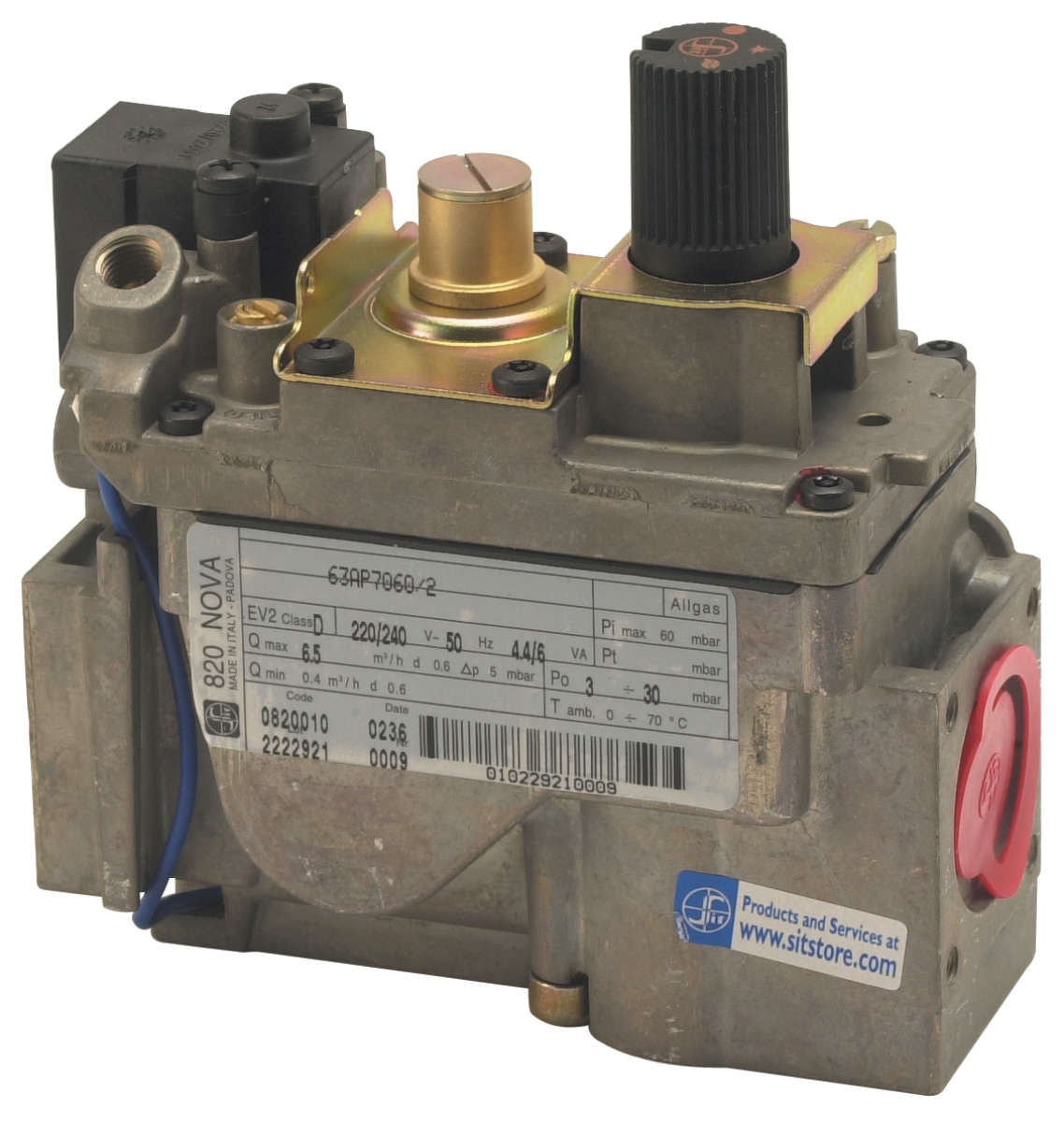
Gas blocking devices (solenoid valves) provide the final safety barrier. These are typically double-staged shut-off valves that allow the main burner valve to open only when all safety interlocks are satisfied. Pressure regulators maintain consistent fuel supply regardless of upstream pressure fluctuations, ensuring burner stability across the operating range.
Essential Control Components and Technical Specifications
The Brahma Relay CM 31 TW30/TS10 exemplifies modern burner control design for atmospheric and fan-assisted burners. This EUROFLA T-series relay features a solid-state ignition device, ionization-based flame monitoring via the rectification property of the flame itself, and dual independent safety contacts in series on the gas valve output. The non-volatile lock-out with manual reset required means that if a safety fault occurs, the system will not attempt automatic restart—a critical safety feature preventing potential hazards from unattended systems. Its two independent safety contacts in series mean that both contacts must close simultaneously for the valve to energize, providing redundancy against contact failure.
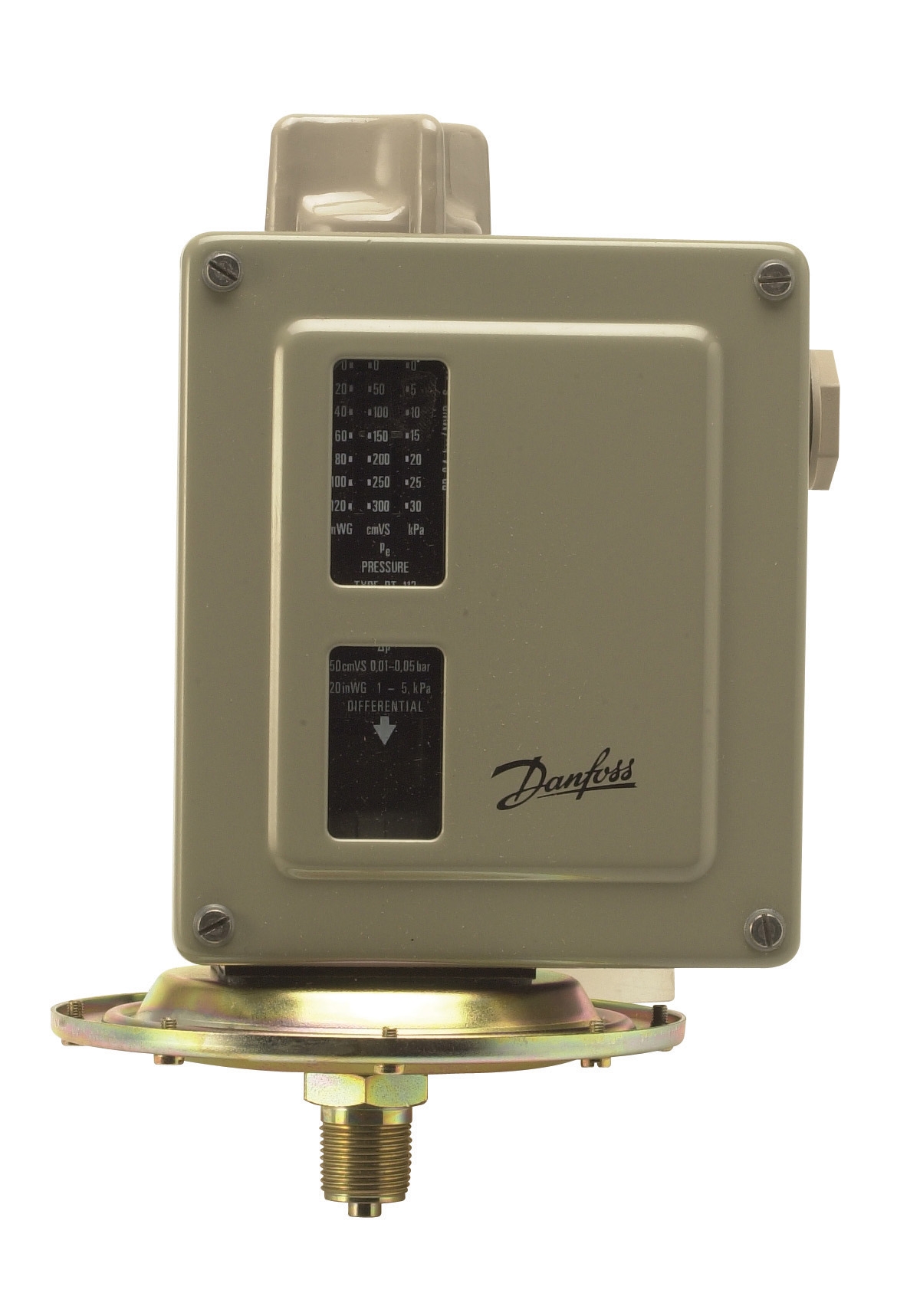
For pressure monitoring, the Danfoss Pressure Switch RT 5 offers exceptional versatility with multiple pressure range options. The RT110 variant covers 0.2 to 3 bar (typical for proving gas inlet pressure on atmospheric burners), while the RT116 extends to 1–10 bar for higher-pressure applications. The RT5's unipolar changeover contact switches based on pressure-commanded logic, allowing it to monitor increasing pressure (e.g., rising gas supply) or decreasing pressure (e.g., air supply failure). This flexibility makes it invaluable for custom installations where standard fixed-range switches don't fit the application.
The Kromschroder Pressure Switch DG 50U/6 represents the high-integrity option for safety-critical systems. Rated SIL 3 and Performance Level e under EN 1854, FM, UL, AGA, and GOST-TR certifications, this switch is suitable for systems where pressure monitoring directly contributes to safety-related functions. Its SIL 3 rating means it can be part of a Safety Integrity Level 3 safety chain—essential for large industrial burners or where multiple burners are sequenced or modulated under automatic control.
For oil-fired or dual-fuel burner installations, the Siemens Cell QRB4B-B050B70A provides dedicated yellow-flame oil burner monitoring. This two-wire thermoplastic sensor is designed for intermittent-duty oil burner applications and includes mounting variants with flanges or soft plastic sleeves for flexible installation. Its front-facing or 90° side-facing viewing direction options allow integration into diverse boiler and burner configurations. Normal and high-response sensitivity versions accommodate different combustion chamber geometries and flame characteristics.
For modulating burner systems or applications requiring variable fuel flow, the Kromschroder Relay BCU 570WC1F1U0K1-E supports both direct ignition and intermittent/continuous pilot ignition modes. Compliant with EN 746-2 and EN 676 standards, this relay manages unlimited-power modulating burners—essential for large commercial boilers or industrial furnaces where burner output must scale with heating demand. Optional bus modules allow networked monitoring and control across multiple burners.
Practical System Integration and Field Installation
When integrating these components into a complete system, sequence and redundancy are paramount. A typical atmospheric burner installation follows this logic:
Pre-ignition phase: The control relay energizes the ignition transformer (typically a 10 kV, 50 mA spark output) and simultaneously opens the pilot gas solenoid. If the application uses a main gas solenoid, this remains de-energized until pilot flame is verified. The ignition attempt window is typically 3–5 seconds; if no flame is detected by the end of this period, the relay enters lockout and requires manual reset.
Flame verification phase: Once pilot flame is confirmed via ionization probe feedback or UV detection, the relay allows power to the main gas solenoid. The main burner ignites from the pilot flame. Continuous flame monitoring ensures that if flame is lost during operation—due to a draft disturbance, fuel supply interruption, or combustion chamber fouling—the relay shuts off gas within 100–200 milliseconds.
Operating phase: With flame proven, the system maintains burner operation as long as thermostat demand is present and all pressure interlocks (air supply, fuel supply) remain satisfied. Pressure switches continuously monitor these conditions; if any switch signals a fault (e.g., blockage in the air intake, drop in gas pressure), the gas valve de-energizes immediately.
Shutdown phase: When thermostat demand ends or a safety fault is detected, the relay de-energizes all solenoids, shutting down the pilot flame and main burner gas supply. Some applications include a post-purge delay to flush unburned gas from the heat exchanger before the system becomes idle.
For fan-assisted and forced-draft burners, air proving is mandatory. A pressure switch monitors the air proving line (typically a small tube sensing burner box pressure or across a venturi). If the fan fails or the intake air path is blocked, the air pressure drop triggers the pressure switch, which signals the relay to prevent ignition or shut down an operating burner. This prevents the accumulation of unignited fuel in the combustion chamber—a fire and explosion hazard.
Installation of flame detection cells requires careful attention to viewing angle, distance from flame, and freedom from fouling. The Siemens QRB4 and similar sensors must see the flame directly; dirt, water vapor, or burner refractory can block the signal. For oil burners especially, regular sensor cleaning is part of preventive maintenance to avoid nuisance shutdowns.
Regulatory Compliance and Regional Standards for Southeast Asia
Southeast Asian HVAC installations increasingly follow European standards (EN 676, EN 746-2) and are adopting CE-marked equipment. Singapore, Malaysia, and Thailand often reference these standards for industrial safety certifications. Equipment bearing CE certification with the relevant EC Type-approval numbers (as documented on the Brahma Relay CM 31) provides traceability and regulatory confidence.
Many local regulatory bodies now require SIL (Safety Integrity Level) certification for pressure switches and control relays used in large or complex systems. The Kromschroder DG 50U/6 SIL 3 rating allows its use in systems designed to meet functional safety requirements, which is increasingly mandated in new industrial installations and retrofit projects across the region.
When specifying controls and safety equipment for Southeast Asia operations, verify:
- CE marking and EC Type-approval documentation for gas-fired equipment
- FM, UL, or local certification marks if the equipment will serve North American or dual-region markets
- Proper pressure range selection (bar vs. mbar vs. inches of water column) matching your design calculations
- Temperature operating ranges; note that tropical Southeast Asia ambient conditions may require equipment rated to 50–55°C or higher
- Voltage availability: many industrial sites use 3-phase power at 400V; verify single-phase control circuits operate reliably at local line voltages
Documentation and commissioning records are critical. Each installation should have a commissioning report showing that all safety functions were tested: ignition spark confirmed, flame detection sensitivity verified, pressure switch setpoints proven, and safe shutdown response validated. This documentation is essential for warranty support, future troubleshooting, and regulatory inspections.
Selection Criteria and Best Practices for Specifying Controls
Matching Controls to Burner Type: Atmospheric burners require controls with integrated ignition and ionization-based flame detection; they operate at very low draft pressure (0.1–0.3 mbar). Fan-assisted burners need pressure switches to monitor burner box pressure and air supply; they tolerate higher inlet gas pressure (0.5–3 bar). Forced-draft industrial burners demand robust modulating controls with high turndown capability and multiple pressure interlocks.
Pressure Range Selection: Undersizing (choosing a pressure switch with range too narrow) causes nuisance trips. Oversizing (range too wide) reduces sensitivity and may miss real faults. For a gas inlet pressure of 1.5 bar, avoid a 0–10 bar switch; instead use the 0.2–3 bar variant of the Danfoss RT 5 for better sensitivity and repeatability.
Redundancy and Safety Architecture: Critical safety functions benefit from dual independent monitoring. Use two pressure switches on the same air line wired in series (both must close to allow burner operation). For flame detection, UV and ionization probes on the same flame provide cross-check capability.
Serviceability: Choose components with established service networks in Southeast Asia. Major brands like Siemens, Honeywell, Danfoss, and Kromschroder have regional distributors and spare parts availability, reducing downtime in case of equipment failure.
Future Expansion: If the installation may later integrate building management systems or remote monitoring, select relays with optional bus modules (as offered on the Kromschroder BCU 570WC1F1U0K1-E) for forward compatibility.
Common Pitfalls and Maintenance Essentials
One frequent mistake is neglecting seasonal commissioning of controls. After the warm months when heating systems sit idle, condensation can form in solenoid valves and control relay terminals. Before firing up for the heating season, run a full safety cycle test and visually inspect solenoid coils for corrosion. Replace any control relays showing signs of moisture ingress (visible condensation inside the terminal cover).
Another pitfall is improper pressure switch installation. These devices must be mounted vertically (unless specifically designed for horizontal mounting) and must not be subjected to vibration or pulsating pressure. Use snubbers or orifice dampers on pulsating gas supply lines to prevent premature switch wear and false triggering.
Flame cell fouling is inevitable in oil-fired systems. Establish quarterly cleaning intervals for UV and ionization sensors; a fouled cell will cause intermittent lockouts or nuisance restarts. Document all cleaning and reset events; trending these tells you if a deeper combustion problem (poor nozzle atomization, burner air adjustment) is developing.
Always test manual reset lockout functionality during commissioning and seasonally thereafter. A relay whose manual reset button is stuck or corroded will require replacement in an emergency, leaving the heating system offline.
Contact 3G Electric for a consultation on your specific burner control and safety requirements. Our team has served industrial customers across Southeast Asia since 1990, and we can help you select, integrate, and maintain control systems that meet local regulations, optimize efficiency, and ensure safe, reliable operation year-round.
Frequently Asked Questions
What's the difference between non-volatile and volatile lockout in burner controls?
Non-volatile lockout (as featured in the Brahma Relay CM 31) means the relay remains locked after a safety fault until the operator manually presses the reset button. This prevents the system from cycling repeatedly if a fault condition persists. Volatile lockout automatically resets after a timeout, making it less safe for unattended systems. Non-volatile is the industry best practice.
How do I know which pressure range to select for a pressure switch?
Calculate your system's normal operating pressure, then choose a switch range where that pressure falls in the middle-to-upper third of the scale. For a 1 bar inlet pressure, select the 0.2–3 bar variant of the Danfoss RT 5 for maximum sensitivity. Consult your burner manufacturer's data sheet for exact pressure setpoints.
Can ionization and UV flame detection be used simultaneously?
Yes. Using both provides cross-verification: ionization is highly sensitive to any combustion but can be fooled by electrical noise, while UV sees only ultraviolet radiation from the flame. On critical systems, both signals can be wired in series so both must confirm flame for the relay to allow burner operation. This redundancy is especially valuable in electrically noisy industrial environments.
What maintenance is required for safety pressure switches?
Annual inspection for corrosion, verification of setpoint accuracy using a calibrated pressure gauge, and cleaning of any water or debris from the sensing port. Pressure switches are not internally serviceable; if a switch becomes unreliable, replacement is the correct action.
Why do some industrial burners require SIL 3 rated controls?
SIL 3 (Safety Integrity Level 3) certification means the component is designed, tested, and documented to operate safely in a defined failure mode. Large burners, multi-burner systems, or installations where a control failure could cause injury or significant asset damage benefit from SIL 3 components. Regulatory bodies in some sectors now mandate SIL 3 for new installations, and the Kromschroder Pressure Switch DG 50U/6 meets this requirement.