Understanding Controls & Safety in HVAC Pressure Systems
Controls & Safety in HVAC burner systems depend fundamentally on accurate pressure monitoring and properly sequenced safety interlocks. For contractors operating in Southeast Asia—where high humidity, rapid temperature swings, and strict energy codes create operational stress—understanding pressure-based safety architecture is essential.
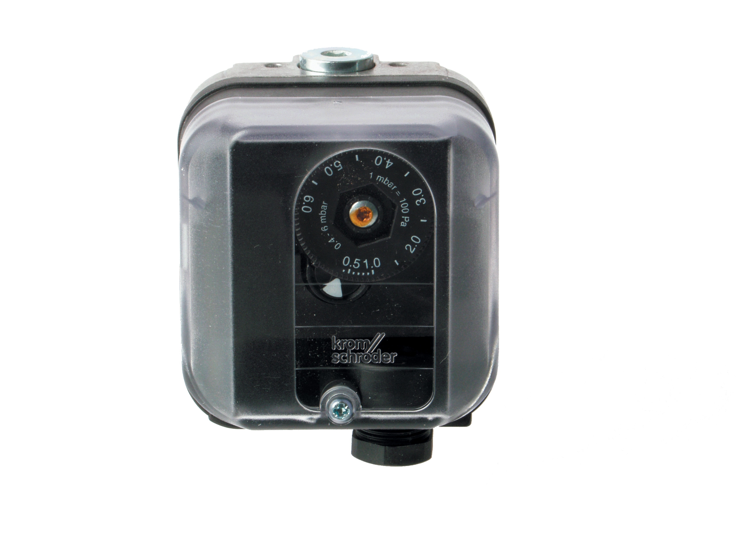
Pressure switches act as the sensory organs of your burner control system. They continuously monitor fuel gas pressure, air pressure differential, and combustion chamber pressure to ensure safe operating conditions before ignition and throughout the burn cycle. Unlike simple on-off switches, modern pressure switches like the Kromschroder DG 50U/6 provide Safety Integrity Level 3 (SIL 3) rated performance, meaning they meet rigorous international standards for failure rates and response reliability.
3G Electric has supplied industrial burner components across Southeast Asia for over 35 years. Our experience shows that pressure monitoring failures account for approximately 40% of unplanned burner shutdowns in the region. The difference between a robust system and a problematic one often comes down to understanding interlock sequencing—the choreographed sequence of safety checks that must occur before your burner ignites.
Pressure Switch Selection and Interlock Sequencing Architecture
Interlock sequencing creates a safety chain: each preceding condition must be satisfied before the next safety check executes. This is not arbitrary—it reflects operational physics and risk management.
A typical sequence in Southeast Asian HVAC installations follows this logic:
Pre-Ignition Phase:
- Air pressure differential check (forced draft fan running, no blockage)
- Fuel gas pressure verification (supply available, regulator functioning)
- Pilot light pressure confirmation (if pilot-type system)
- Flame detection circuit armed and tested
- Combustion chamber purge cycle complete (3–5 air changes)
- Spark ignition or hot surface igniter energized
- Pilot flame established (detected within 3–5 seconds)
- Main flame detected and stabilized
- Flame signal confirmed and steady
- Continuous pressure monitoring active
- Temperature limits enforced
- Modulation signals responding to demand
The Kromschroder DG 50U/6 pressure switch is purpose-built for this sequencing. Its SIL 3 / Performance Level e certification means it's been independently validated to safely interrupt fuel supply if pressure drops below safe thresholds. The switch can be configured with adjustable setpoints, allowing contractors to tune the system for specific gas types (natural gas vs. LPG—common in Southeast Asia) and pressure regimes.
In practice, a contractor must understand why each interlock exists:
- Air pressure differential interlock: Without adequate combustion air, fuel accumulates in the chamber. Ignition creates dangerous pressure spikes or incomplete combustion with carbon monoxide production.
- Fuel pressure interlock: Low pressure means inadequate atomization, poor flame shape, and risk of flame extinction mid-cycle.
- Purge interlock: In Southeast Asia's humid environment, condensation in combustion chambers is common. The purge cycle removes moisture and unburned fuel vapors before ignition.
- Flame detection interlock: Confirms actual flame presence. A UV detector (like those in the Siemens LFL 1.622) works in bright sunlight; ionization detection works in all conditions but requires periodic electrode cleaning in dusty environments.
Practical Installation and Tuning for Southeast Asian Conditions
Southeast Asia's climate—high humidity (60–95% year-round), temperatures 25–40°C, salt air in coastal areas—creates specific installation challenges that affect pressure monitoring reliability.
Pressure Switch Placement and Impulse Lines:
Contractors often make critical errors in routing impulse lines from the burner to the pressure switch. In humid environments:
- Use copper or stainless steel tubing, never plastic. Plastic degrades and becomes brittle under UV and heat cycling.
- Slope impulse lines downward toward the burner at 1:4 minimum grade. Water condensation in horizontal or upward-sloping lines creates false pressure readings.
- Install a small snubber (damper) if impulse line exceeds 3 meters. Long lines resonate, causing nuisance shutdowns.
- Keep impulse lines away from hot surfaces (>60°C). Heated air causes pressure signal drift.
A pressure switch has two setpoints: the cut-in (make) pressure and cut-out (break) pressure. The gap between them is hysteresis—typically 0.3–0.5 bar on gas pressure switches. Hysteresis prevents chattering: if a pressure switch cuts out at exactly 0.5 bar and cuts in at exactly 0.5 bar, it will oscillate 10–20 times per second as pressure naturally fluctuates around the setpoint.
When commissioning a Kromschroder DG 50U/6 in a humid tropical environment, account for barometric pressure variation. Atmospheric pressure at sea level is 1.013 bar; in highland Southeast Asian regions (elevation 500–2000 m), atmospheric pressure drops 5–20%. This affects both absolute pressure and differential pressure readings. If your system is in a highland area, recalibrate using local barometric pressure as the reference.
Gas Block Integration with Pressure Monitoring:
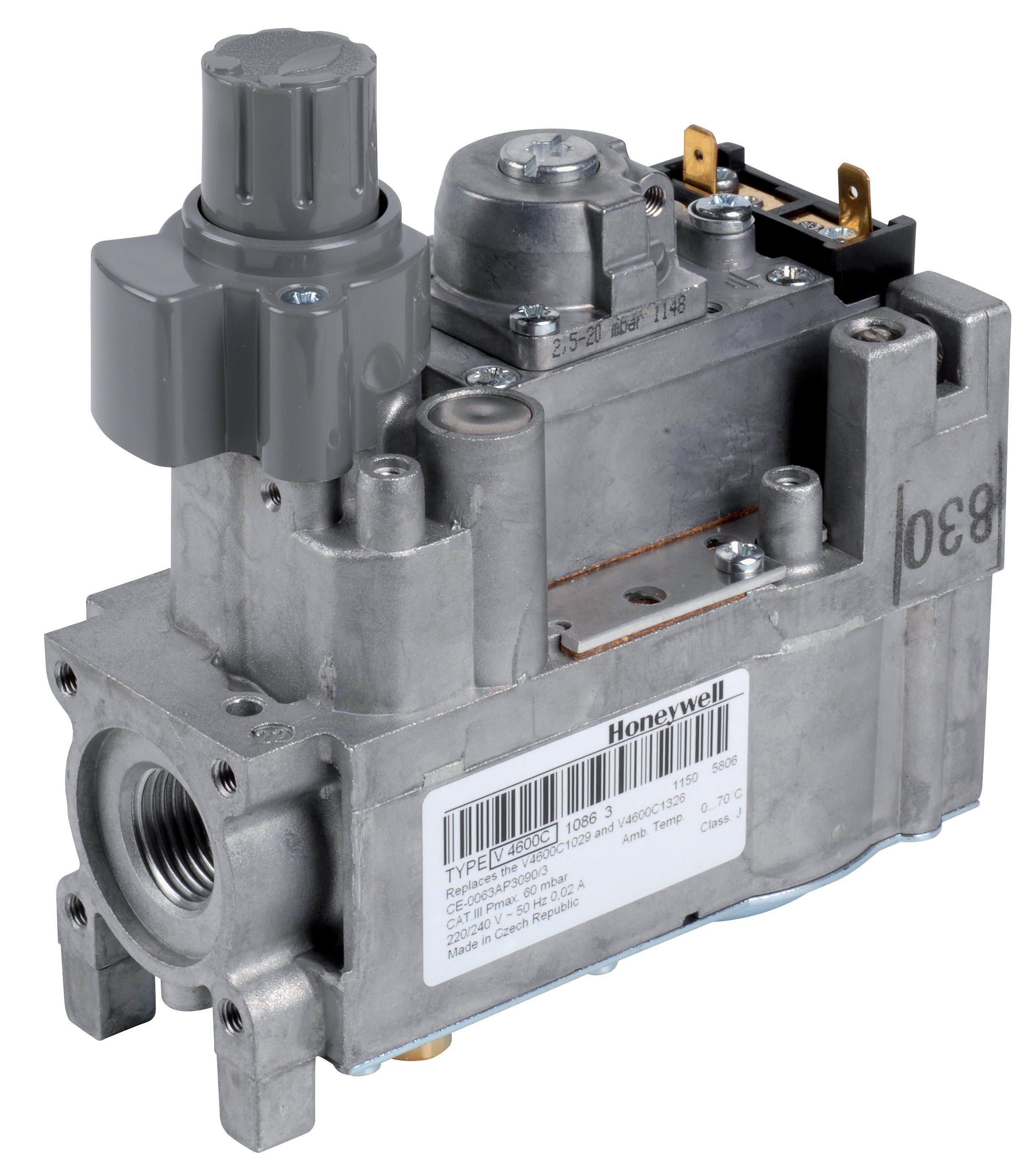
The Honeywell VK 4105 C 1041 U gas block is an electric modulating pressure regulator that works in tandem with pressure switches. The regulator maintains constant outlet pressure to the burner; the pressure switch monitors that outlet pressure to confirm the regulator is functioning. If the switch detects pressure has drifted outside acceptable limits, it signals the control relay to shut down the system.
In tropical installations, ensure the gas block's solenoid coil has adequate ventilation. Solenoid coils can overheat if ambient temperature exceeds 45°C, particularly in poorly ventilated equipment rooms common in Southeast Asia. Install a small axial fan (12V or mains) to force air circulation if the equipment enclosure temperature exceeds 40°C.
Safety Relay Systems and Flame Detection Integration
Modern safety interlocks rely on control relays that execute the sequencing logic. The Kromschroder BCU 570WC1F1U0K1-E relay is a burner control unit rated for EN 746-2 and EN 676 standards, with support for direct ignition and both intermittent and continuous pilot modes.
The relay receives electrical signals from all safety devices:
- Pressure switch (dry contact, normally open)
- Flame detector (UV or ionization signal)
- Temperature sensor (analog 4–20 mA signal)
- Manual reset safety switch (if installed)
The relay processes these inputs and executes the programmed sequence. For example:
```
ON DEMAND REQUEST:
IF air_pressure_OK AND fuel_pressure_OK THEN
START purge_cycle (30 seconds)
IF purge_complete THEN
ENERGIZE igniter (5 seconds)
WAIT_FOR flame_detection
IF flame_detected THEN
ENERGIZE main_fuel_solenoid
MONITOR pressure AND flame CONTINUOUSLY
ELSE
SHUT_DOWN (ignition failed lockout)
END IF
END IF
ELSE
SHUT_DOWN (initial safety check failed)
END IF
```
The Siemens LFL 1.622 offers similar functionality with integrated UV and ionization flame monitoring. UV detection is faster (response time ~0.1 seconds) but can be affected by ambient UV from skylights or high-altitude sun. Ionization detection (response time ~0.5–1 second) is immune to external light but requires clean electrodes. In dusty Southeast Asian environments, UV detection is often more reliable because you eliminate electrode fouling issues.
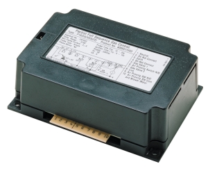
The Pactrol Housing P 16 DI CE flame control module operates at 230V (standard in Southeast Asia) with 12 kV ignition output and 10 MJ energy per spark. This is sufficient for igniting natural gas, LPG, and dual-fuel applications common in the region. The 10 MJ specification is important: if your ignition energy is below 8 MJ, ignition failures increase dramatically in humid air (humidity acts as an electrical insulator).
Maintenance and Diagnostics in High-Humidity Environments
Southeast Asia's humidity accelerates component aging. Pressure switches, relays, and solenoid coils degrade faster than in temperate climates.
Quarterly Pressure Switch Verification:
Use a calibrated pressure gauge connected to the impulse line. Compare the gauge reading with the pressure switch signal state:
- If the gauge shows safe pressure but the switch is open (de-energized), the switch may be faulty.
- If the gauge shows low pressure but the switch is closed (energized), the impulse line is blocked by condensation—blow out with dry compressed air.
For ionization-type detectors, clean the sensing electrodes with a dry cloth and isopropyl alcohol. Do not use abrasive pads; scratched electrodes collect dirt faster. For UV detectors, inspect the UV window; replace if yellowed or cloudy (UV transmission degrades 50% per year in tropical sunlight).
Solenoid Valve Cycling:
Electromagnetic solenoid valves in gas blocks can stick if not cycled regularly. If a system has been idle for more than 2 weeks, manually cycle the solenoid 3–5 times before returning to automatic operation. This prevents pilot pressure buildup that can cause delayed opening.
With 35+ years of experience supplying HVAC components across Southeast Asia, 3G Electric recommends establishing a preventive maintenance schedule: monthly visual inspection, quarterly pressure verification, semi-annual full system testing, and annual component replacement for switches and solenoids that show age-related drift.
Understanding Controls & Safety through the lens of pressure monitoring and interlock sequencing transforms troubleshooting from guesswork to systematic diagnosis. Your burner system will operate reliably, pass safety audits, and provide years of service in Southeast Asia's challenging environment.