Burner Control System Integration & Commissioning: A Practical Guide for Industrial Operations
Industrial burner systems represent critical infrastructure in manufacturing, heating, and processing applications across the globe. Yet many procurement and plant engineering teams struggle with the practical integration of burner control systems—the electronic interface that ensures safe, efficient, and reliable combustion. This guide addresses the real-world challenges of selecting, integrating, and commissioning burner control systems for industrial applications. We'll explore the technical foundations, examine specific control architectures, walk through real application scenarios, and establish best practices that help you avoid costly downtime and safety issues. Whether you're specifying equipment for a new installation or upgrading existing combustion infrastructure, understanding control system integration is essential to achieving operational excellence.
Understanding Burner Control System Architecture
A modern burner control system operates as the "nervous system" of your combustion equipment, continuously monitoring operating conditions and making millisecond-level adjustments to maintain safe, efficient combustion. At its core, a burner control system integrates three functional layers: the sensing layer (flame detection and operational monitoring), the control logic layer (electronic relays and decision-making circuits), and the actuation layer (valve commands, fan speed modulation, and fuel flow adjustment).
The sensing layer captures critical real-time data through flame detection sensors, pressure transducers, and temperature monitors. These inputs flow into the control logic layer—typically an electronic relay or control module—where sophisticated algorithms evaluate conditions against programmed safety parameters. Within milliseconds, the system decides whether to maintain combustion, modulate fuel flow for efficiency, or execute a controlled shutdown if safety thresholds are exceeded. Finally, the actuation layer translates these decisions into physical actions: opening fuel isolation solenoids, adjusting air dampers, or modulating burner firing rates.
Understanding this architecture is critical because each layer must operate in precise coordination. A mismatch between sensor response time, control logic processing speed, and valve actuation creates reliability problems and safety risks. This is particularly important in industrial settings where burners operate continuously or cycle frequently. The integration process—connecting sensors to control relays, configuring timing parameters, and validating safety interlocks—determines whether your system delivers reliable, efficient operation or becomes a source of unplanned downtime.
Flame Detection and Safety Relay Configuration
Flame detection represents the critical safety foundation of any burner control system. Industrial regulations globally require continuous flame supervision—the burner must prove that fuel is burning before allowing continued fuel flow, and must immediately shut off fuel if flame is lost. The three primary flame detection technologies differ significantly in cost, reliability, and application suitability.
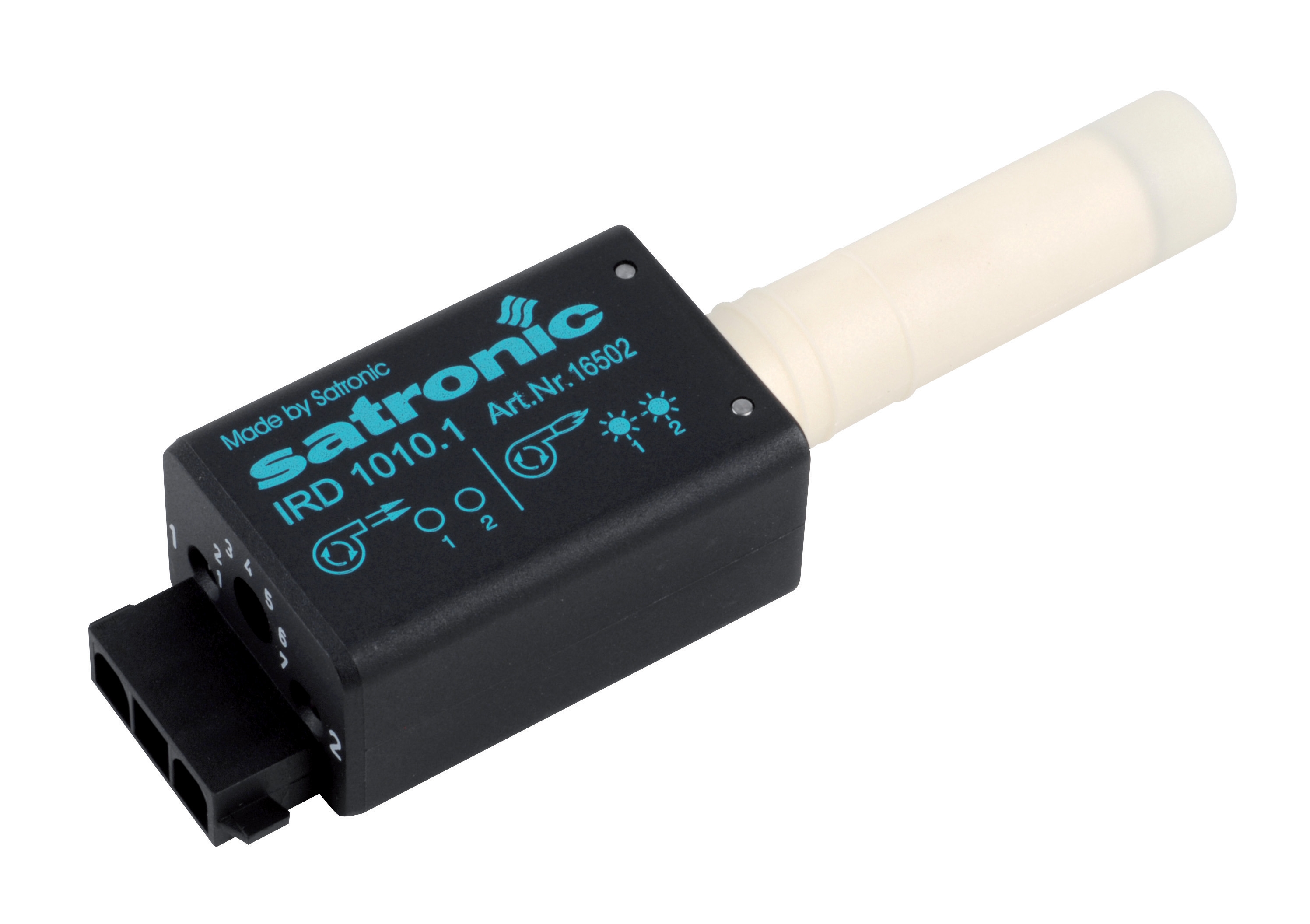
Infrared (IR) flame detectors like the CBM IRD 1010 blue cell use optical sensors to detect the infrared radiation emitted by fuel flames. These sensors excel in applications with heavy fuel oils or biomass where flame color and intensity are pronounced. The IRD 1010 sensor specifically detects the characteristic signature of blue fuel flames, making it highly immune to false signals from ambient light or reflective surfaces. Installation requires careful positioning to optimize flame view while protecting the sensor from excessive heat and combustion residue.
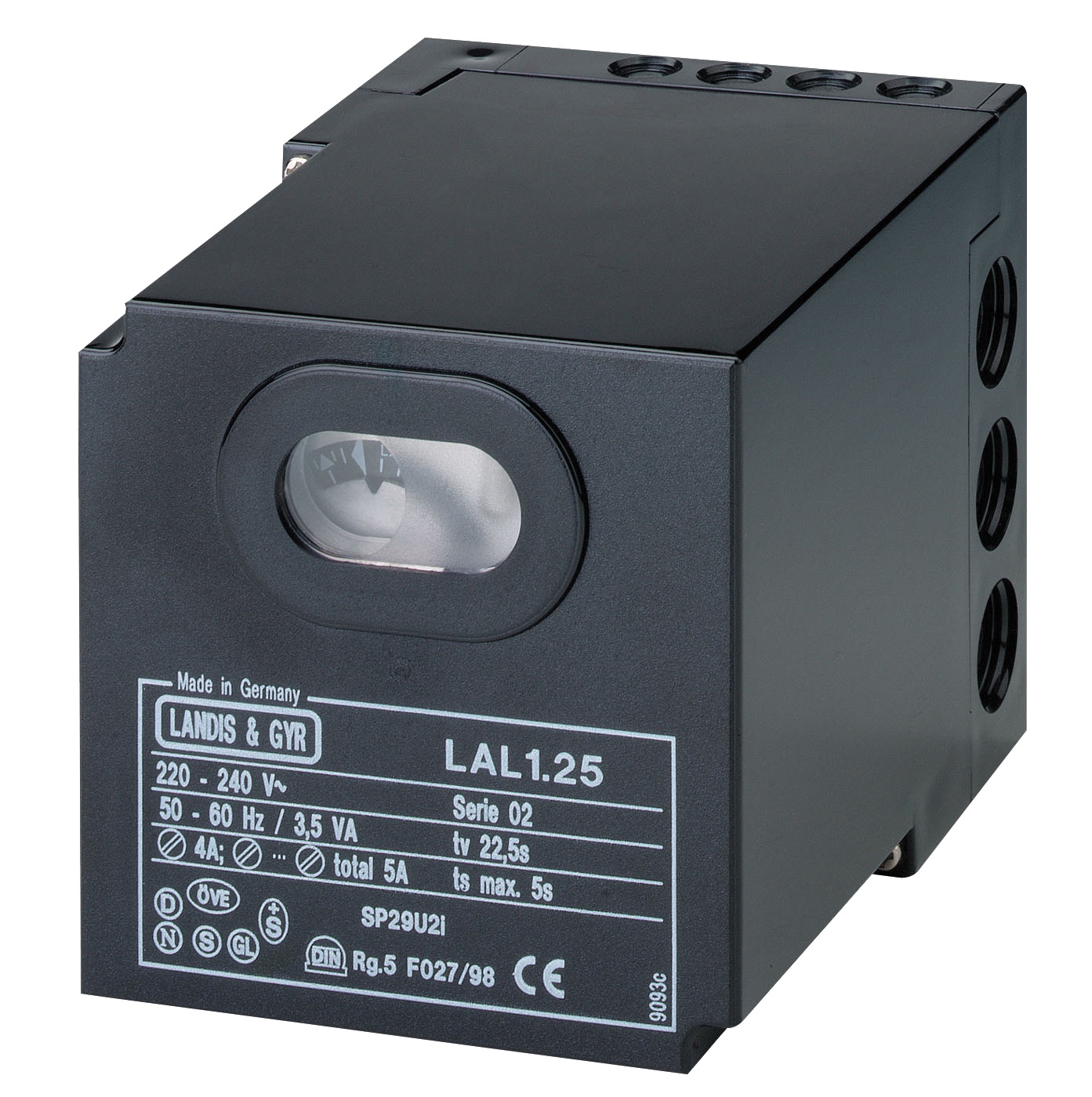
Safety relay modules form the intelligent decision-making core of your control system. The CBM LAL 2.14 relay represents a dedicated safety control system designed specifically for fuel burner applications. This relay integrates flame signal processing, air pressure supervision (detecting fan failure or air path blockage), and air damper modulation control into a single compact module. The LAL 2.14 provides non-volatile memory lockout—when a safety fault occurs, the system requires manual intervention to reset, preventing automatic restart after certain fault conditions and ensuring operators verify the cause before resuming operation.
For gas burner applications, the CBM SM 592.2 relay offers automatic control specifically designed for atmospheric and fan-assisted gas burners in intermittent operation. This EUROBOX series relay manages the safety sequence, including pilot light supervision, main gas valve timing, and fan motor control. Configuration parameters—ignition delay timing, flame establishment time, safety shutdown delay—must be carefully matched to your specific burner characteristics and fuel supply characteristics. Incorrect timing creates problems ranging from nuisance shutdowns to unsafe operating modes.
Practical Integration: Connecting Components and Commissioning Sequences
The actual integration process follows a disciplined sequence. First, you must map the physical connections: power supply, flame sensor input, pressure switch inputs (if equipped), valve command outputs, and modulation control outputs. Wiring installation demands careful attention to grounding, shielding of sensor signals, and physical separation of low-voltage control wiring from high-voltage power circuits to prevent electrical noise from corrupting flame detection signals.
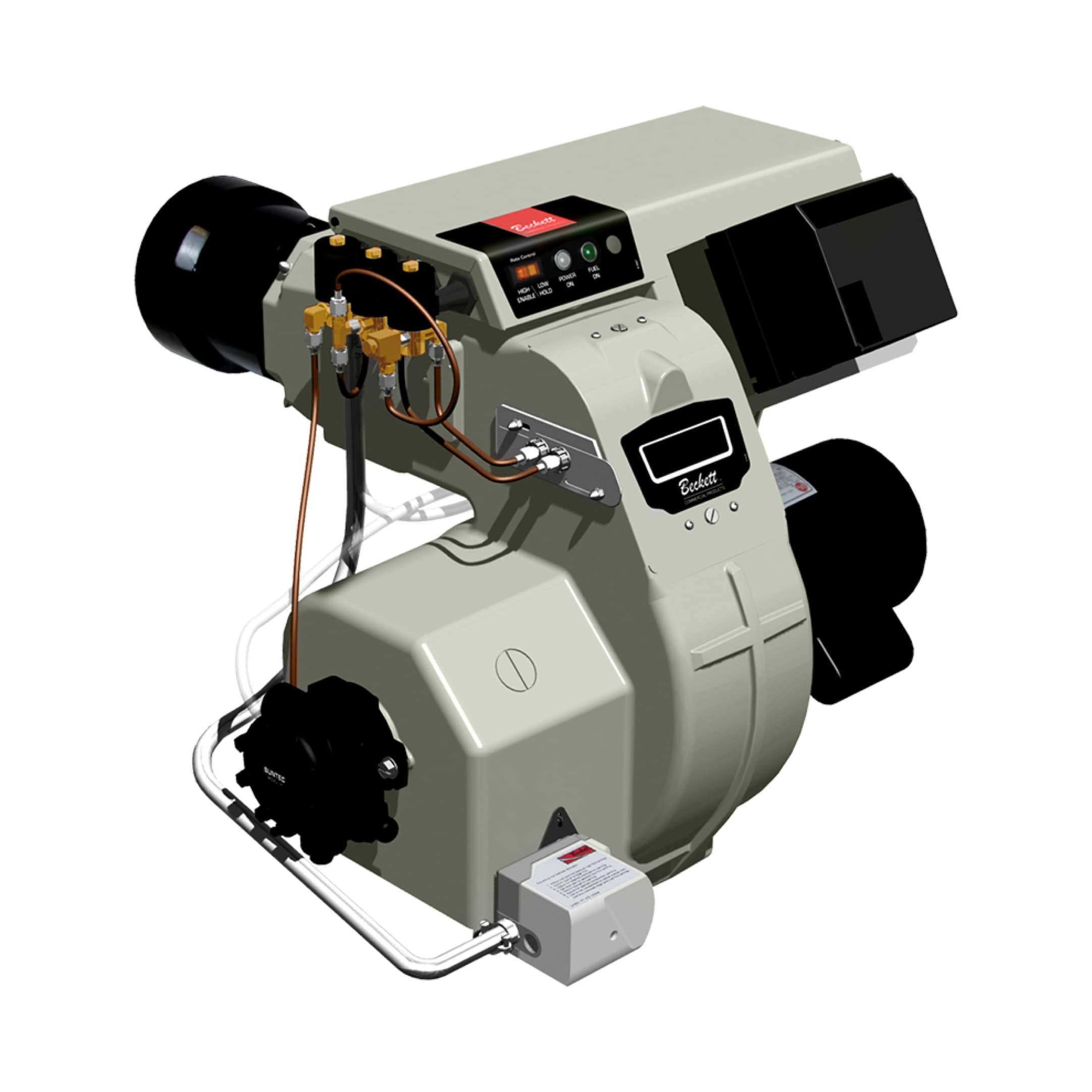
Consider a mid-sized industrial heating system using a modulating FBR BURNER GAS X5 burner. This burner operates with a 370W fan motor and achieves power output ranging from 69.8 kW minimum to 349 kW maximum through proportional fuel valve modulation. Integrating this burner requires: (1) configuring the control relay to match the burner's modulation response curve, (2) commissioning the flame sensor for reliable detection across the entire firing range, and (3) calibrating air/fuel ratio adjustments for efficiency across different load levels.
The commissioning sequence itself requires systematic validation. Begin with pre-ignition verification: confirm electrical power, test manual reset functions, validate all safety interlocks. Progress to ignition trials with burner fuel supply isolated—verify ignition spark and flame signal response. Only then introduce fuel under controlled low-fire conditions, gradually increasing to full load while monitoring flame stability and control responsiveness. Electronic control relays like the CBM CM391.2 relay provide built-in diagnostic features that display fault codes and flame signal strength during this process, allowing technicians to optimize sensor positioning and control calibration.
Real-World Application Scenarios and Integration Challenges
Consider a food processing facility in Southeast Asia operating continuous hot water heating for sanitation and process requirements. The facility upgraded from a simple on-off burner to a modulating system to improve fuel efficiency and reduce temperature swings. Integration required installing the FBR GAS X5 burner with proportional modulation capability, then configuring a control relay that accepts a 0-10V modulation signal from their building automation system. The challenge: synchronizing the burner's modulation response (which lags 2-3 seconds during transitions) with the water temperature sensor input to the facility's main control system. Solution: tuning the relay's proportional-integral-derivative (PID) parameters to create smooth modulation transitions without overshoot or hunting.
An industrial boiler installation at a ceramics kiln facility faced a different challenge: unreliable flame detection causing false shutdowns. Root cause analysis revealed that IR flame detection was receiving reflected signals from the bright kiln refractory, creating noise in the flame signal. The integration solution involved repositioning the IRD 1010 sensor to view the flame directly while installing a sighting tube with reduced diameter to limit spurious reflections. Additionally, the facility upgraded to a more sophisticated LAL 2.14 safety relay with adjustable flame signal filtering that could distinguish true flame signal from electrical noise.
Selection Criteria and Integration Best Practices
Match control system capability to burner type and application duty. Gas burners in intermittent operation (regular on-off cycling) require different control strategies than continuous-duty or modulating applications. Atmospheric burners generate different flame characteristics than fan-assisted burners. Always select a control relay specifically designed for your burner type—mixing applications creates reliability and safety problems.
Establish clear communication parameters with your fuel supplier. Fuel supply pressure, temperature stability, and contaminant levels significantly affect flame stability and sensor performance. Industrial applications sometimes encounter fuel supply variations that laboratory specifications don't predict. Coordinate with your fuel supplier to understand typical operating ranges and potential upset conditions.
Design your integration with maintenance accessibility. Safety relays, flame sensors, and pressure switches require periodic inspection and occasional replacement. Specify mounting locations that allow technicians to access components without extensive equipment disassembly. Plan for sensor calibration and cleaning intervals—combustion byproducts accumulate on optical sensors over time, degrading signal quality.
Document commissioning parameters thoroughly. Record the specific control relay settings used during successful commissioning: ignition delay, flame establishment time, modulation parameters, and any sensor positioning adjustments made. This documentation becomes invaluable when troubleshooting future problems or commissioning replacement equipment.
Getting the Integration Right: Next Steps
Burner control system integration represents a critical intersection of mechanical engineering, electrical safety, and combustion science. The systems and components outlined here—from flame detection sensors to safety relays—are designed to work together, but only when properly selected, installed, and commissioned. A poorly integrated control system becomes a source of ongoing frustration: nuisance shutdowns, efficiency losses, and deferred maintenance that compounds reliability problems.
At 3G Electric, we've served industrial customers globally since 1990, helping engineering teams navigate precisely these integration challenges. Whether you're evaluating burner control equipment, troubleshooting an existing system, or planning a facility upgrade, our technical team brings hands-on experience across diverse industrial sectors and applications. Contact us today to discuss your specific burner control integration requirements—we'll help you design a system that delivers reliable, efficient combustion operation and meets your facility's unique operational demands.