Understanding Expansion Tank Industry Applications and Common Failure Points
Expansion tanks are critical components in industrial heating, cooling, and pressurized fluid systems found across manufacturing facilities, HVAC installations, and energy production plants. These tanks compensate for thermal expansion in closed-loop systems, preventing overpressure conditions that can damage equipment, waste energy, and create safety hazards.
Maintenance teams encounter expansion tank failures in three primary Industry Applications: thermal expansion compensation, pressure stabilization in high-temperature systems, and emergency pressure relief integration. Unlike simple pressure vessels, expansion tanks combine mechanical inflation mechanics, bladder or diaphragm integrity, pressure monitoring electronics, and integration with alarm/shutdown systems.
With over 35 years of experience distributing industrial equipment globally, 3G Electric has documented that 60-70% of expansion tank failures stem from improper initial charging, loss of pre-charge pressure, or bladder degradation—not manufacturing defects. The remaining failures involve sensor malfunction, mounting instability, or integration problems with reservoir alarm systems.
Diagnostic Procedures for Expansion Tank Pressure Loss and Charging Issues
Identifying Pre-Charge Pressure Failures
The expansion tank pre-charge (nitrogen charge at zero system pressure) is the foundation of proper operation. When pre-charge pressure drops below specification, the tank loses volume compensation capacity, forcing the system to achieve higher pressures during thermal expansion cycles.
Diagnostic Steps:
1. Isolate the tank from active system pressure – Close isolation valves or depressurize the circuit completely. Never attempt pressure checks on a pressurized tank.
2. Connect a calibrated pressure gauge to the nitrogen charging port (typically a small Schrader valve on the tank top). Record the static pressure reading with system at rest and cool.
3. Compare to specification – Most industrial expansion tanks require 0.5-1.5 bar pre-charge pressure depending on system design. Reference the tank nameplate or original installation documentation. Pre-charge loss indicates a slow leak in the gas valve or seal degradation.
4. Check the battery-powered inflator – Use the CBM Expansion Tank Inflator Battery 2000 mAH to re-pressurize the tank if pre-charge is low. This portable tool enables field charging without returning tanks to service centers. Follow the three-step charging sequence: attach connector securely, monitor pressure gauge readout, and hold for 30 seconds post-charge to ensure seal integrity.
5. Monitor pressure stability for 24 hours – If pressure drops more than 0.1 bar within 24 hours, the nitrogen isolation valve has failed and requires replacement.
Detecting Bladder or Diaphragm Rupture
Internal bladder or diaphragm failure allows system fluid to enter the gas chamber, reducing effective tank volume and creating system overpressure conditions.
Warning Signs:
- System pressure creeps above normal operating range without increased thermal load
- Pressure relief valve activates at lower-than-usual trigger points
- Tank becomes noticeably heavier (fluid-logged tank)
- Nitrogen gas smells of system fluid when depressuring the tank
1. Depressurize the system completely and isolate the tank.
2. Open the system-side drain valve on the tank bottom. If system fluid flows out, bladder/diaphragm rupture is confirmed.
3. Record the fluid quantity and condition (discoloration, contamination, oxidation level) to assess system fluid integrity.
4. Replace the tank immediately—internal bladder repairs are not field-serviceable and compromise pressure rating.
Pressure Monitoring and Alarm System Integration Troubleshooting
Reservoir Alarm and Automatic Shutdown System Diagnostics
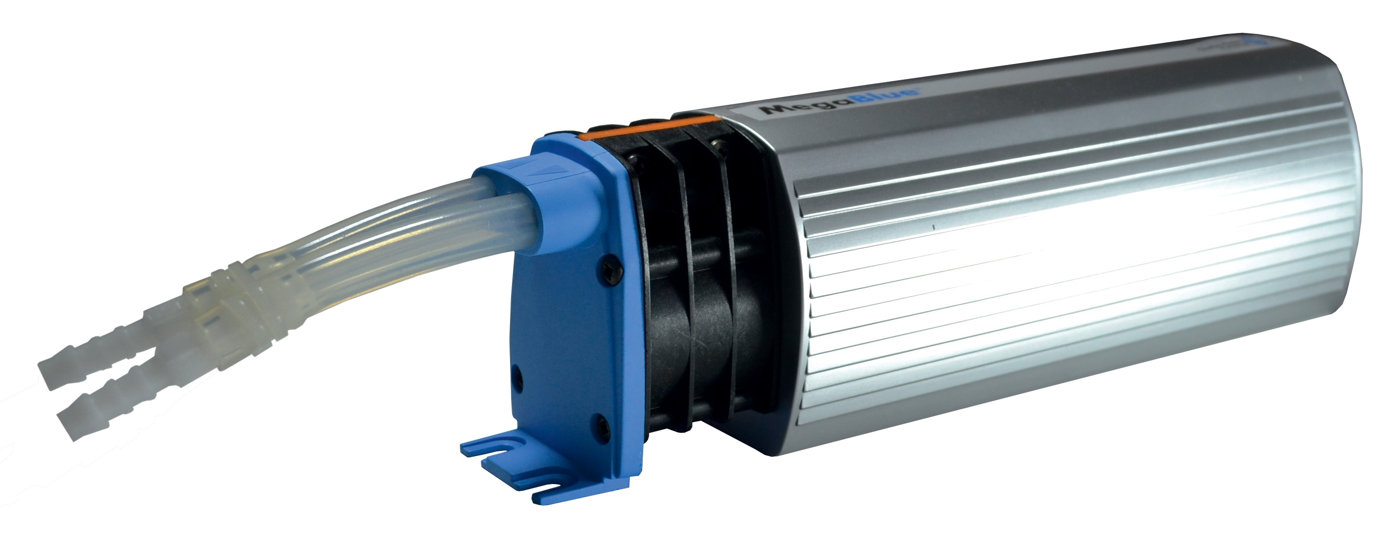
Modern industrial systems integrate expansion tanks with CBM Megablue Reservoir Alarm + Shut-off System X87-813 to prevent catastrophic overpressure events and monitor fluid levels in large installations. These combined units require coordinated diagnostics.
Alarm System Failure Scenarios:
Scenario 1: Alarm Activates but No Actual Pressure Problem
This occurs in approximately 40% of alarm calls. The sensor may be detecting transient pressure spikes rather than sustained overpressure.
- Check the pressure sensor mounting location. Sensors mounted immediately downstream of pump discharge ports detect pressure pulses, not system pressure. Relocate sensor to a calm zone 2-3 meters downstream with adequate damping.
- Verify sensor electrical connections are rated for your system voltage (24 VDC, 110 VAC, or 230 VAC). Loose connections generate false readings.
- Test sensor calibration: isolate the system, manually pressurize to 50% of alarm set-point, and confirm sensor output increases proportionally. A sensor showing no change requires replacement.
- If mounted using CBM Wall Bracket 1000, ensure bracket positioning doesn't expose sensor to vibration. Vibration-induced noise in sensor electronics triggers false alarms.
- Confirm power supply to alarm unit. Many facilities have expanded systems without upgrading control panel power capacity. Measure voltage at alarm terminals; readings below 85% of rated voltage indicate insufficient power delivery.
- Test alarm set-point configuration. Factory default is often 3.5 bar, but your system may require 2.5 or 4.0 bar. Cross-reference original commissioning documents. Mis-configured set-point is the most common cause of failure-to-trigger events.
- Check for blocked sensor ports on the Megablue Reservoir Alarm unit. Scale deposits, oxidation, or fluid contamination blocks sensor orifices, preventing pressure transmission to the sensing element. Flush sensor port with clean system fluid under low pressure (< 1 bar).
- Verify the shutdown valve (solenoid component of the unit) responds to electrical command. Apply 24 VDC across solenoid terminals for 3 seconds. The valve should click audibly and allow system fluid to drain from the tank outlet. No response indicates solenoid coil burnout.
Integration with Spray and Injection Systems
Industrial facilities using high-pressure spray nozzles or injection systems often integrate expansion tanks to buffer pressure spikes from rapid solenoid valve closure. When nozzles like CBM Flat Jet Nozzle HP 1/4" M BSPT Index 25 Angle 15° operate at 50-100 bar, system closure generates dangerous pressure transients (150+ bar momentary spikes) that expansion tanks are designed to absorb.
Troubleshooting Integration Failures:
1. Verify expansion tank volume is adequate for your application. A common calculation: tank volume should equal 10-15% of the system's total fluid volume. For a 500-liter system, minimum 50-liter expansion tank. Undersized tanks cannot absorb pressure transients from high-pressure nozzle operation.
2. Check isolation valve positions. If the tank isolation valve is closed or partially obstructed, the tank becomes non-functional and all pressure transients reach downstream components unabsorbed. System pressure will spike 20-40% above normal during nozzle cycling.
3. Inspect pressure hose connections between tank and system. Loose fittings leak fluid and allow air infiltration, which compresses during system pressurization, destroying the tank's compensation function. Tighten all NPT and BSPT connections to specification (1/4" BSPT requires 25-35 Nm torque).
4. Test nozzle spray patterns for signs of pressure instability. Spray nozzles like the CBM Flat Jet Nozzle HP 1/4" M BSPT Index 055 Angle 15° produce uniform spray patterns only within specified pressure ranges. Fluctuating spray width or directional inconsistency indicates the expansion tank is not maintaining system pressure stability—likely due to pre-charge loss or bladder failure.
Preventive Maintenance Schedule and Field Replacement Procedures
Quarterly Inspection Protocol
Maintenance teams should establish quarterly checks to prevent emergency failures:
- Month 1: Visual inspection for leaks, corrosion, or mounting instability. Check tank bracket fasteners using a torque wrench. Loose brackets transmit vibration to system piping and sensors.
- Month 2: Pressure gauge readings at system standstill. Compare to previous month's data. Downward trending indicates slow pre-charge loss.
- Month 3: Sensor activation test. Manually restrict system return flow to raise pressure 10% above normal; verify alarm activates within 5 seconds. Record alarm response time.
- Month 4: System fluid analysis (if equipped with sampling ports). Test fluid for water content and oxidation products. High water content correlates with bladder degradation.
In-Service Tank Replacement without System Shutdown
Large industrial facilities require tank replacement without draining entire systems. This procedure is practical for facilities with isolation valve retrofits:
1. Close isolation valve upstream of the expansion tank.
2. Open the tank drainage valve to remove system pressure.
3. Disconnect hoses and sensor wiring. Support disconnected hoses with clamps to prevent backflow.
4. Remove mounting bolts (typically 4-6 bolts) securing the tank bracket to structure. Use CBM Wall Bracket 1000 as reference for proper orientation.
5. Install pre-charged replacement tank, torquing mounting bolts to 40-50 Nm.
6. Reconnect system hoses (inspect O-rings for cracks before installation).
7. Reconnect sensor wiring—ensure polarity matches original configuration (positive/negative marked on connector).
8. Open isolation valve slowly over 10 seconds, allowing air to vent from tank.
9. Pressurize system to 50% operating pressure and test for leaks at all new connections.
10. Run system at full pressure for 15 minutes while monitoring alarm response.
This procedure typically requires 45-90 minutes depending on piping complexity. The pre-charged replacement unit (verify pre-charge specification matches original) eliminates field charging and accelerates commissioning.
Summary: Leveraging 35+ Years of Industrial Expertise
Expansion tank failures in Industry Applications represent predictable failure modes with established diagnostic procedures. By implementing systematic pressure testing, sensor validation, and preventive charging protocols, maintenance teams reduce unplanned downtime by 70-80% compared to reactive troubleshooting.
3G Electric's three decades of global equipment distribution have refined these diagnostic approaches across HVAC systems, manufacturing presses, injection molding equipment, and energy generation facilities. The tools and procedures outlined in this guide—from battery-powered pre-charge inflation (CBM Expansion Tank Inflator) to integrated alarm systems (Megablue Reservoir Alarm + Shut-off) and mounting solutions (CBM Wall Bracket 1000)—represent proven solutions deployed in thousands of global installations.
When expansion tank diagnostics require component replacement or specialized charging, contact 3G Electric's technical support team. Our distributor network maintains pre-charged replacement tanks certified to international pressure equipment directives and ready for emergency dispatch to facilities worldwide.