Pilot Light Controls & Safety Systems: A Technical Guide for Industrial Burner Operations in Singapore
Pilot light control systems form the backbone of safe industrial burner operations across Singapore's manufacturing, food processing, and energy sectors. These systems provide flame verification, ignition sequencing, and critical safety interlocks that prevent dangerous gas discharge and equipment damage. Understanding the technical architecture of pilot lights, flame detection mechanisms, and thermocouple-based safety systems is essential for maintenance personnel, plant engineers, and equipment operators who manage heating systems, boiler controls, and combustion equipment. This guide explores the core components, technical specifications, and operational best practices that ensure reliable and compliant burner control systems.
Core Architecture of Pilot Light Control Systems
Pilot light control systems operate on a hierarchical safety principle: a small, continuously or intermittently lit flame serves as both an ignition source for the main burner and a primary safety indicator. The system continuously verifies the presence of this pilot flame before allowing fuel delivery to the main burner. This verification happens through flame detection technology integrated with safety relays that monitor the flame signal.
The typical control sequence begins with a spark or igniter energizing the pilot burner. Once the pilot flame is established, a flame sensor detects the presence of combustion and signals the safety relay to energize the main gas solenoid valve. If the pilot flame extinguishes for any reason—due to draft, draft hood blockage, or component failure—the safety relay immediately de-energizes the main fuel supply within 2-4 seconds, preventing unburned gas accumulation.
Key operational parameters in pilot light systems include:
- Flame establishment time: Typically 2-5 seconds for pilot ignition
- Flame signal stability: Must remain stable within ±20% variation for safe operation
- Proof-of-flame response: Detection signal must occur within 100 milliseconds of flame presence
- Safety shutdown time: Complete fuel cutoff within 4 seconds of flame loss
- Operating temperature range: Most components rated for -15°C to +60°C ambient conditions
In Singapore's tropical industrial environment, where ambient temperatures remain consistently between 25-35°C with high humidity levels, pilot light control systems must be specified with adequate corrosion resistance and thermal stability. Burner control systems designed for this climate incorporate stainless steel components and enhanced insulation to maintain reliable operation throughout extended service intervals.
Technical Components: Flame Detection and Thermocouple Safety Integration
Modern pilot light systems employ three primary flame detection technologies, each with distinct operational characteristics and safety advantages.
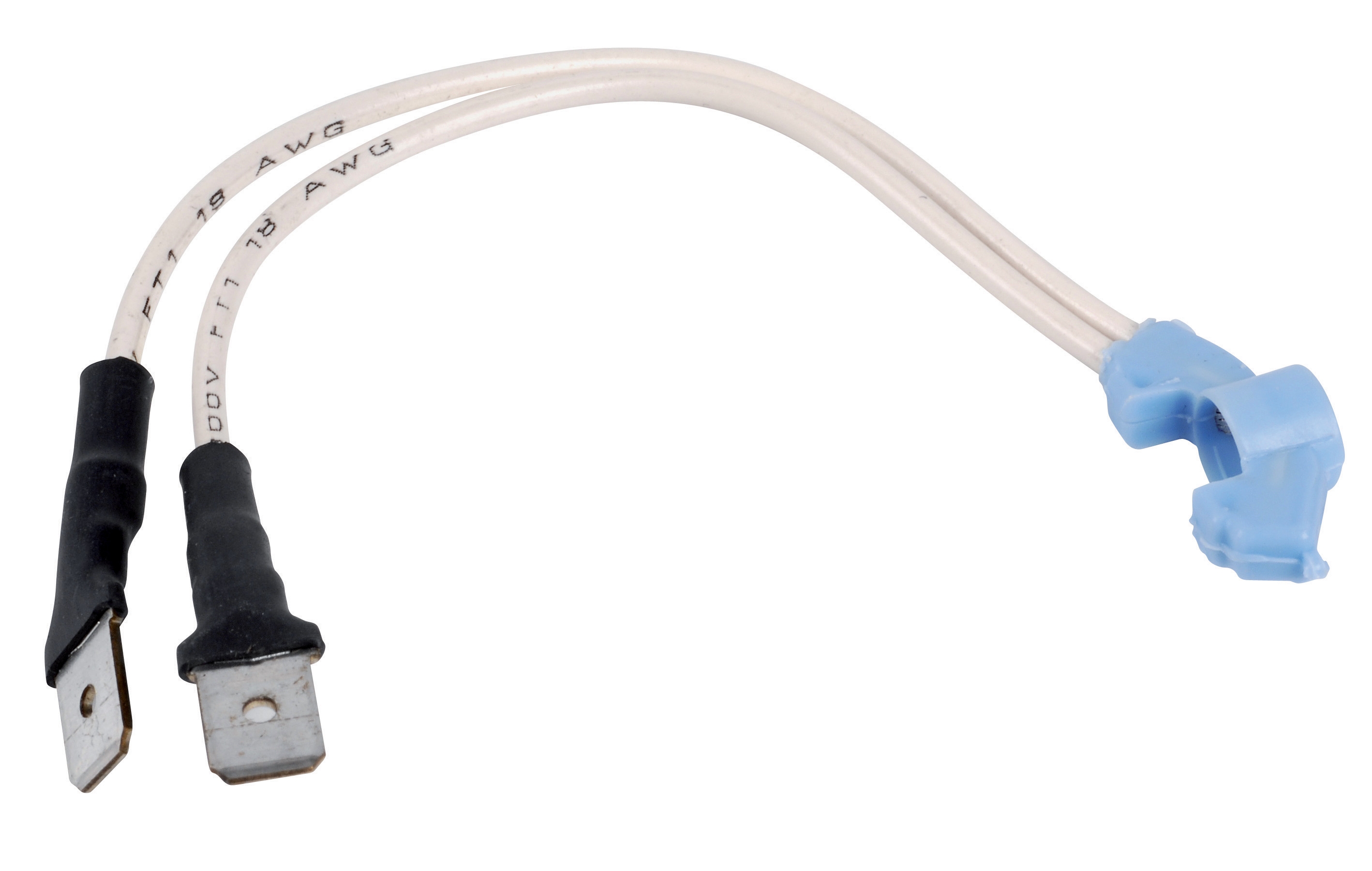
Thermocouple-based detection remains the most widely deployed technology for intermittent pilot applications. The thermocouple generates a millivolt signal (typically 15-30mV) when heated by the pilot flame. This signal powers a safety relay directly without requiring external electrical power, making it inherently fail-safe. Products like the CBM Thermocouple Safety are engineered for maximum operating temperatures of 815°C at the target tip for Q334A configurations, with the orifice assembly rated to 340°C. The thermocouple's thermal mass and response time create a built-in delay that prevents nuisance shutdowns from momentary flame flicker.
Ultraviolet (UV) flame detection offers rapid response to flame presence and loss. UV sensors detect the ultraviolet radiation emitted by hydrocarbon combustion, typically in the 200-300nm wavelength range. The CBM Cell QRA 10C represents this detection class, providing response times under 1 second and exceptional resistance to false signals from ambient radiation. UV sensors perform particularly well in outdoor or semi-outdoor installations where draft variations are common.
Infrared flame oscillation detection analyzes the characteristic flicker frequency of hydrocarbon flames (typically 5-15Hz). This method virtually eliminates false ignition signals from hot surfaces or electrical discharge, providing the highest selectivity available. The CBM Relay TMG 740-3 63.55 integrates infrared flame detection specifically designed for high-efficiency forced-air gas and mixed fuel burners operating in intermittent mode with one or two combustion heads.
All flame detection methods feed signals into safety control relays that perform diagnostic functions and execute shutdown sequences. These relays monitor flame signal quality, verify proper system operation during startup sequences, and maintain continuous self-diagnostics to detect wiring faults or sensor degradation. Safety relays must be certified to relevant standards—typically EN 60730-2-8 or equivalent—ensuring they perform their safety functions reliably.
Real-World Application Examples in Singapore Industrial Operations
Consider a food processing facility in the Jurong Industrial Estate operating continuous hot water boilers for sterilization processes. The facility specifies pilot light controls with UV-based flame detection (QRA 10C) rather than thermocouples due to frequent steam exposure that causes rapid thermocouple corrosion. The UV sensor's immunity to moisture and superior response time (under 1 second versus 3-5 seconds for thermocouples) provides faster burner ignition during demand changes, improving process responsiveness and reducing energy waste from extended pre-heat cycles.
A different example involves a medium-sized petrochemical facility managing multiple furnaces with infrared flame detection. The facility selected the TMG 740-3 relay because its advanced diagnostics detect incipient thermocouple failure weeks before complete sensor breakdown. The relay's self-diagnostics reduce unexpected shutdowns from 3-4 per year to fewer than one per year, dramatically improving production uptime and reducing maintenance costs.
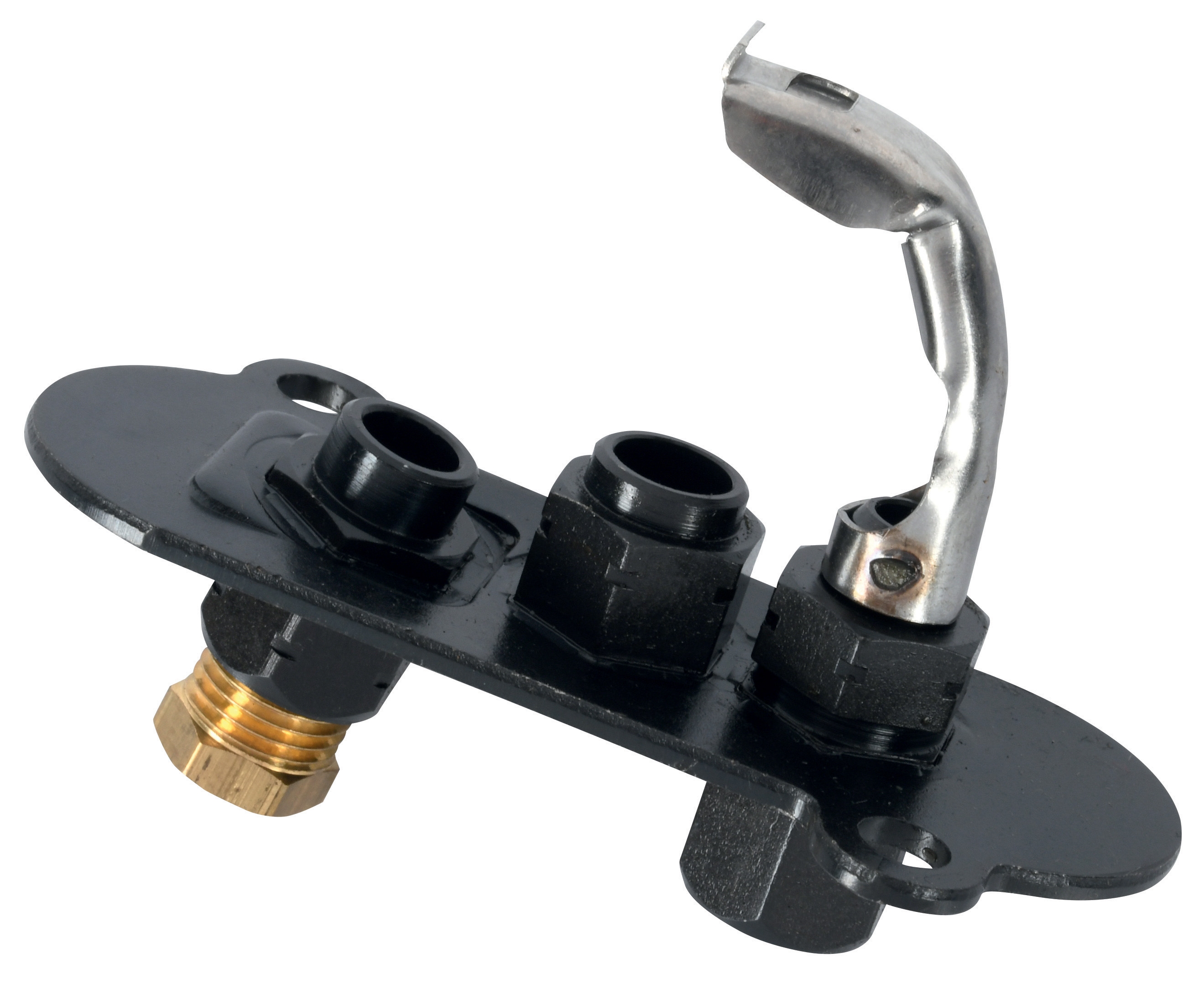
A third scenario involves a commercial laundry in Changi retrofitting old atmospheric pilot burners with universal pilot light assemblies. The CBM Universal Pilot Light 1 Flame 3 Positions allows installation in three orientations without performance degradation, eliminating the need for custom mounting brackets and reducing installation time from 6 hours to 2 hours per burner. The pilot's aluminum oxide igniter plugs withstand the thermal cycling from 50+ daily ignition cycles without deterioration.
Selection Criteria and Best Practices for Pilot Light Control Systems
Duty cycle classification fundamentally shapes component selection. Intermittent pilot systems—where the pilot extinguishes during main burner shutdown—demand robust ignition reliability and fast flame establishment. Continuous pilot systems maintain the pilot flame constantly, reducing ignition stress but increasing fuel consumption. Most industrial applications in Singapore favor intermittent pilots for energy efficiency.
Flame detection method selection depends on installation environment and response requirements:
- Choose thermocouples for cost-sensitive applications with stable draft conditions and low humidity exposure
- Select UV sensors for outdoor installations, applications with significant draft variation, or high-moisture environments
- Specify infrared detection where maximum selectivity and fastest response times are critical
Thermocouple compatibility demands attention to detail. Pilot burners like the CBM Pilot Light 2 Flames 0140015 are engineered for use with specific thermocouple models. SIT pilot burners achieve optimal performance exclusively with SIT thermocouples, preventing impedance mismatches that reduce signal strength. Substituting thermocouples from different manufacturers risks unreliable flame detection and nuisance safety shutdowns.
Environmental rating considerations are critical in Singapore's climate. All control and safety components should be specified with IP54 minimum enclosure ratings to protect against tropical moisture ingress. Components operating in high-temperature environments (near furnace or boiler casings) require higher ambient temperature ratings—typically 60°C or above—to maintain calibration stability.
Maintenance access and diagnostics reduce long-term operating costs. Modern relays with LED status indicators and built-in test functions allow technicians to verify proper operation without test equipment. The ability to swap thermocouples rapidly (under 5 minutes) minimizes emergency shutdown duration when sensors require replacement.
Ensuring Regulatory Compliance and Operational Safety
Singapore's industrial safety framework requires all burner control systems to comply with relevant international standards including EN 60730-2-8 (safety devices), EN 298 (automatic burner control systems), and Energy Code requirements for equipment efficiency. Pilot light systems must incorporate redundant safety features: flame detection with automatic shutdown, manual reset requirements after 3 consecutive ignition failures, and operator visibility into control system status through indicator lights or integrated displays.
Regular maintenance intervals—typically 12 months for comprehensive system inspection and thermocouple replacement every 3-5 years—preserve safety system reliability. Documentation of maintenance activities and flame detection signal strength measurements create audit trails demonstrating compliance with Singapore's workplace safety regulations.
Pilot light control systems represent the critical interface between user demand and safe combustion process execution. Understanding flame detection principles, thermocouple signal transmission, and safety relay diagnostics empowers maintenance teams to operate these systems confidently and troubleshoot common issues systematically. Whether managing a single burner or a complex multi-fuel heating system, proper pilot light control specification, installation, and maintenance protects both equipment investment and personnel safety.
3G Electric has served Singapore's industrial equipment needs since 1990, supplying authentic gas controls and burner safety components from leading manufacturers. Our technical team provides system selection guidance, compatibility verification, and support for pilot light retrofits and new installations. Contact our team today to discuss your burner control requirements or schedule a system health assessment.