How to Select and Install Pilot Light Controls & Safety Systems in Singapore Industrial Burners
Pilot light control systems form the critical foundation of safe and reliable industrial gas burner operations. Whether you're managing heating systems, cooking equipment, or large-scale combustion installations across Singapore, understanding the proper selection and installation of pilot light controls and safety devices is essential for regulatory compliance and operational efficiency. This guide provides technical professionals with actionable specifications, component selection criteria, and installation methodologies for implementing robust burner control systems that meet Singapore's industrial safety standards.
Understanding Pilot Light Control Systems and Safety Architecture
A pilot light control system operates as an integrated safety and operational framework designed to ignite, monitor, and maintain the primary burner flame. The system architecture typically comprises four essential functional layers: ignition control, flame detection and verification, safety interlocking, and operational sequencing.
The ignition control layer initiates the pilot flame through a high-voltage spark or heating element. The flame detection layer—employing either ionization electrodes, ultraviolet (UV) sensors, or infrared flame detection—continuously monitors flame presence and intensity. Safety interlocking mechanisms, including solenoid valves and control relays, create a fail-safe pathway that cuts fuel supply if flame loss is detected. Finally, operational sequencing coordinates timing between pilot ignition, main burner ignition, and flame stabilization.
In Singapore's industrial environment, where equipment operates continuously under demanding conditions, pilot light control systems must demonstrate exceptional reliability. Modern systems employ redundant flame detection—utilizing dual-sensor configurations—to ensure that any single component failure triggers immediate fuel shutoff. This redundancy is particularly critical in mixed-fuel burner installations (gas/oil combinations) common in Singapore's refineries, manufacturing facilities, and large commercial installations.
The control relay serves as the computational and decision-making hub of this system. It receives input signals from flame sensors, temperature monitors, and pressure switches, then orchestrates the opening and closing of solenoid valves, ignition systems, and damper motors in precise sequences. The CBM Relay TMG 740-3 63.55 exemplifies this approach, specifically engineered for intermittent-duty burners with one or two combustion heads, supporting multiple flame detection technologies including ionization electrodes, UV cells, and infrared oscillation detectors.
Technical Components: Flame Detection, Thermocouples, and Control Integration
Flame detection technology directly impacts system responsiveness and safety margins. Ionization electrode systems monitor the electrical conductivity of the flame, offering cost-effective detection with response times under 200 milliseconds. UV sensors detect ultraviolet radiation emitted during combustion, providing superior performance in high-ambient-temperature environments and delivering response times below 150 milliseconds. Infrared oscillation detection monitors the characteristic frequency of flame flicker, offering immunity to false ignition from electrical transients or ambient radiation sources.
The CBM Cell QRA 10C represents state-of-the-art UV flame detection technology. This sensor provides dedicated flame monitoring for gas and oil burners integrated with Siemens safety control units. The QRA series delivers robust performance in challenging industrial environments, with spectral response tuned specifically to combustion UV signatures while rejecting false-positive triggers from ambient light sources.
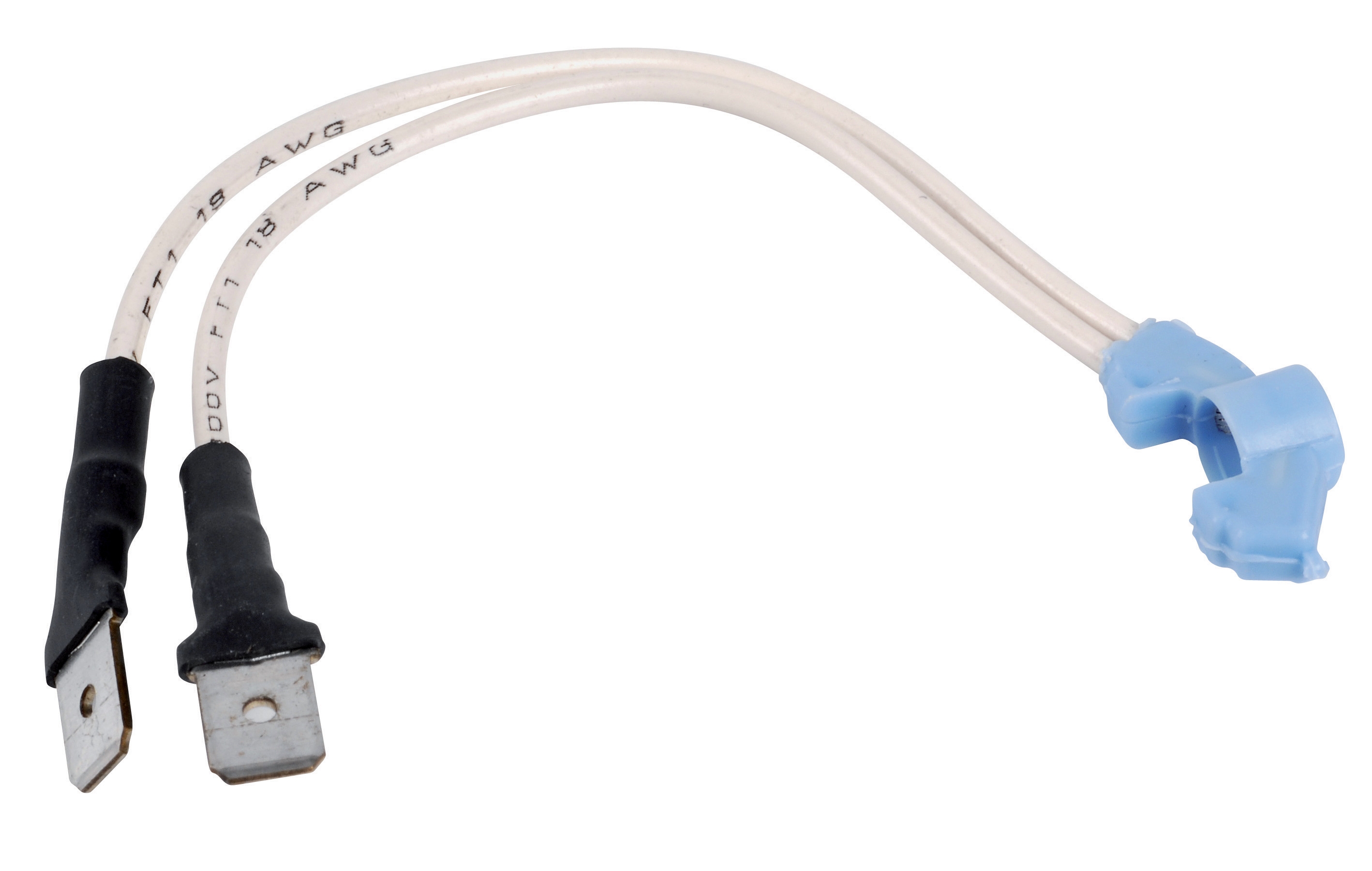
Thermocouples form the secondary safety verification system in most pilot light assemblies. A thermocouple generates a small DC voltage (typically 15-40 mV) proportional to flame temperature, creating a direct physical relationship between flame presence and electrical output. This voltage energizes holding circuits in the control relay, maintaining solenoid valve operation. When flame extinguishes, thermocouple voltage collapses, de-energizing the holding circuit and closing fuel supply within 1-2 seconds.
The CBM Thermocouple Safety is engineered for Q334 and Q385 series pilot burners, specified for maximum operating temperatures of 815°C at the target tip and 340°C at the orifice assembly. For correct operation, exclusive use of manufacturer-specified thermocouples is mandatory—mismatched thermocouple resistance creates incorrect voltage profiles and compromises safety margins.
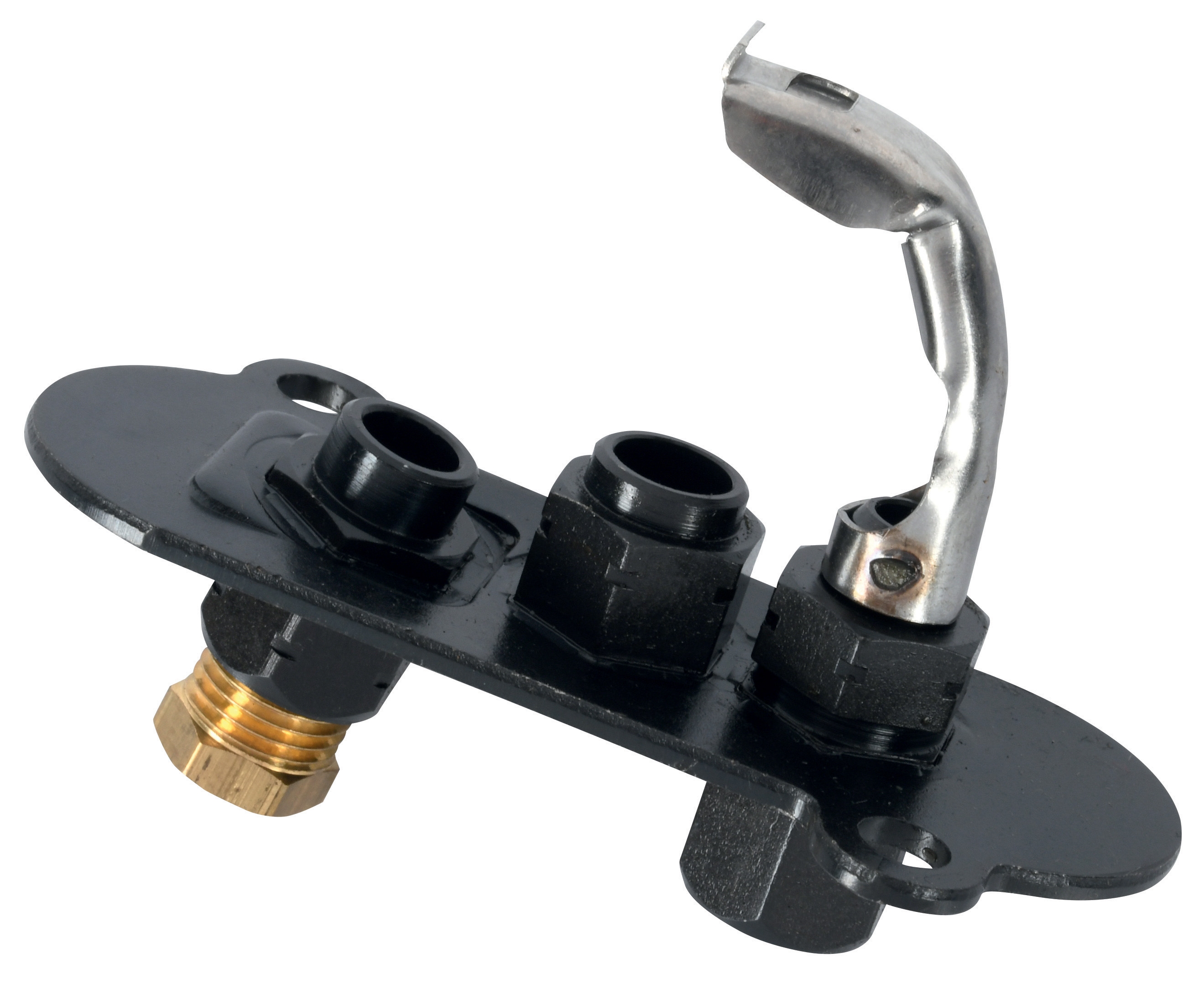
Pilot light assemblies such as the CBM Universal Pilot Light 1 Flame 3 Positions and CBM Pilot Light 2 Flames integrate highly-insulated aluminium oxide igniter plugs that withstand thermal shock and impact stress. These assemblies permit rapid thermocouple substitution for maintenance, incorporate corrosion-resistant construction, and operate with minimal acoustic signature—critical for industrial environments where noise levels are regulated.
Step-by-Step Installation and Commissioning Procedure
Step 1: Pre-Installation System Assessment
Verify burner specifications against control system ratings. Document fuel type (natural gas, propane, oil, or mixed-fuel), burner firing rate (typically measured in kW or BTU/h), and combustion head configuration (single or dual-head). Cross-reference flame detection technology compatibility—ensure UV sensors are specified for the burner's spectral output.
Step 2: Component Layout and Wiring Diagram Development
Create a detailed control circuit schematic showing the pilot light assembly, flame detection sensor, thermocouple, main solenoid valve, ignition transformer, and control relay mounting. For systems utilizing the CBM Base for MA 86, establish proper grounding and ensure 50/60 Hz supply voltage matches local Singapore industrial standards (typically 380V three-phase or 230V single-phase).
Step 3: Physical Component Installation
Mount the pilot light burner assembly on the burner head, ensuring the igniter plug aligns with the fuel injection point. Secure the thermocouple against the flame envelope without direct contact. Install the flame detection sensor—for UV cell installations, ensure the optical window has unobstructed line-of-sight to the flame and is protected from liquid fuel spray.
Step 4: Electrical Integration and Safety Relay Commissioning
Connect the thermocouple signal leads (typically 1-2 milliampere circuits) to dedicated low-voltage terminals on the control relay. Wire the flame detection sensor to the sensor input, observing polarity. Program the control relay logic—modern units like the TMG 740-3 support configurable delay timers (typically 0-10 seconds) and flame detection response thresholds. Test the fuel shutoff response by manually blocking the flame detection sensor; the solenoid valve should close within 2 seconds.
Step 5: Functional Testing and Documentation
Conduct a complete ignition sequence: energize the ignition transformer, verify pilot flame ignition within 5 seconds, confirm thermocouple voltage generation, and test main burner ignition timing. Document all sensor readings, valve response times, and igniter plug current draws (typically 8-12 mA). Perform a flame-loss test by extinguishing the pilot light manually; verify automatic fuel shutoff and inability to re-energize the main burner without manual reset.
Selection Criteria and Best Practices for Singapore Industrial Applications
Choosing appropriate pilot light controls requires alignment with operational duty cycle and environmental exposure. Intermittent-duty systems (typical in cooking and heating applications) tolerate longer ignition delays compared to continuous-duty industrial burners that demand response times under 500 milliseconds. Verify the flame sensor's ambient temperature tolerance—for installations near furnaces or in exhaust-gas-recirculation environments, UV sensors often outperform ionization electrodes, which may suffer false shutdowns in high-temperature conditions.
In Singapore's humid tropical climate, corrosion resistance is paramount. SIT-brand pilot burners utilize highly-insulated aluminium oxide components specifically engineered for moisture and salt-air environments. Thermocouple selection should account for the burner's orientation and fuel atomization method—oil burner thermocouples experience different flame temperature profiles compared to gas-fired units and must be specified accordingly.
For systems requiring manual or automatic ignition sequencing, consider control relay systems that support configurable logic. The CBM Relay TMG 740-3 accommodates both intermittent and continuous duty cycles and supports three flame detection modalities, providing flexibility for future system modifications or fuel-type conversions. Ensure all components carry CE marking or equivalent Singapore-recognized safety certifications.
Maintenance accessibility should influence component selection. Pilot light assemblies permitting rapid thermocouple changes reduce downtime during scheduled replacements. When specifying burner control systems, prioritize designs that segregate diagnostics (allowing technicians to verify sensor function without full system shutdown) from safety interlocking (fuel shutoff mechanisms that remain independent of diagnostic circuits).
Conclusion and Next Steps
Implementing robust pilot light controls and safety systems protects both equipment investment and personnel safety across Singapore's diverse industrial sectors. By understanding flame detection technologies, thermocouple operation, control relay logic, and proper commissioning procedures, maintenance professionals can design systems that deliver reliable ignition, continuous flame verification, and fail-safe fuel shutoff under all operational conditions.
The integration of UV flame sensors, temperature-responsive thermocouples, and intelligent control relays creates redundant safety pathways that exceed regulatory requirements while enabling predictive maintenance through continuous sensor diagnostics. Whether upgrading existing burner systems or commissioning new installations, following systematic selection and installation procedures minimizes commissioning delays and ensures compliance with Singapore's industrial safety standards.
For technical specifications, compatibility verification, or commissioning support for controls and safety components, contact 3G Electric's technical team. As an authorized distributor of premium industrial control equipment since 1990, we provide direct access to product documentation, application engineering support, and rapid component availability across Singapore. Our specialists can assist with system design review, component selection validation, and on-site commissioning consultation to ensure your pilot light control system operates at peak safety and efficiency. Reach out to discuss your specific burner control requirements today.