Understanding Motor & Drive System Failures in Industrial Operations
Motor and drive systems power industrial fluid equipment, yet failures often go undiagnosed until catastrophic breakdown occurs. As a distributor with 35+ years of experience serving global industrial operations, 3G Electric recognizes that procurement engineers must understand the relationship between motor performance, pump efficiency, and system reliability.
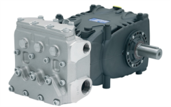
Motor failures typically stem from three sources: mechanical overload, electrical degradation, and thermal stress. When you specify equipment like the Pratissoli KF30 (40 kW, 106 L/min) or MW40 (85 kW, 211 L/min) high-performance pumps, the driving motor becomes critical to sustained operation. A single motor failure cascades through your entire fluid system, affecting pressure delivery, spray accuracy, and production efficiency.
Procurement engineers must evaluate not just motor specifications—power rating, RPM, voltage class—but also how motors integrate with drive systems, control electronics, and mechanical loads. This guide provides actionable troubleshooting frameworks to diagnose failures before they impact production schedules.
Diagnostic Framework: Identifying Motor Performance Degradation
Mechanical Symptom Analysis
Begin diagnostics by correlating observed mechanical symptoms with underlying motor conditions:
Vibration and Noise Indicators:
- Excessive vibration (>7.1 mm/s velocity per ISO 20816) signals bearing wear, rotor imbalance, or misalignment
- High-frequency squealing indicates bearing lubrication failure; low-frequency rumbling suggests mechanical looseness
- When operating Interpump E1D1808 pumps (8 L/min at 180 bar), vibration directly affects seal integrity in downstream components
- Mitigation: Install vibration monitoring at motor feet using accelerometers; establish baseline readings during commissioning
- Monitor winding temperature using embedded sensors; shutdown triggers typically set at 130°C for Class B insulation
- Thermal imaging reveals hot spots on motor frame (>55°C ambient differential) indicating winding faults or rotor bar cracks
- Sustained temperature >95°C without load increase signals cooling system failure or ventilation blockage
- Action: Clean motor cooling fins monthly in dust-prone environments; verify ambient temperature stays 10°C below rated rise
- Measure three-phase current using clamp meters; unbalanced phases (>5% deviation) indicate winding short circuits
- Current surge >150% of nameplate during normal operation signals increased friction from bearing degradation
- For pump systems, compare motor current against system pressure gauges—rising current with stable pressure indicates motor efficiency loss
Electrical Fault Detection
Electrical diagnostics require systematic testing with appropriate instrumentation:
Insulation Resistance Testing (Megohmmeter):
- Measure phase-to-ground and phase-to-phase resistance using 500V megohmmeter for motors <1 kW, 1000V for larger units
- Acceptable baseline: >100 MΩ for new motors; >10 MΩ for operating motors
- Trending is critical: a 50% drop in one week indicates imminent failure; gradual decline over months allows planned replacement
- Document humidity conditions during testing—moisture dramatically affects results
- Continuity testing identifies open-phase conditions without energizing the motor
- Resistance values between phases should match within ±5% for three-phase motors
- Compare against nameplate resistance specifications; deviations >10% suggest thermal damage or manufacturing defect
- Non-invasive ultrasonic bearing testers detect friction changes 4-6 weeks before mechanical failure
- Baseline frequency signatures (20-60 kHz band) should remain constant; new spectral peaks indicate spalling
- Thermal imaging of bearing housings reveals temperature asymmetry earlier than vibration analysis
Preventive Maintenance & Service Protocols
Scheduled Maintenance Intervals
Establish maintenance cycles aligned with equipment duty class and operating environment:
Weekly Visual Inspections:
- Check motor frame temperature using infrared thermometer; record readings and trend data
- Visually inspect cooling air pathways for blockages (lint, dust accumulation)
- Listen for unusual acoustic signatures during startup and under load
- Verify mounting bolts remain tight; vibration loosens fasteners progressively
- Clean motor air vents and cooling fins with compressed air; avoid high-pressure washing that forces contaminants into bearings
- Inspect cable insulation for cracking, cuts, or abrasion (particularly at strain relief points)
- Verify ambient temperature stays within motor nameplate rating; install supplemental cooling if room temperature exceeds limits
- Check grounding continuity from motor frame to facility ground using multimeter (<1 Ω acceptable)
- Perform megohmmeter insulation resistance testing; establish trending baseline
- Measure all three-phase currents under controlled load and document actual power factor
- Ultrasonically inspect bearings to detect developing friction signatures
- Review temperature logs and current profiles for gradual degradation trends
- Engage qualified technicians for full motor performance testing including:
- Power factor analysis (target: >0.85)
- Vibration analysis per ISO 20816 standards
- Rotor bar resistance testing (for induction motors)
- Bearing endoscopic inspection
- Document all baseline parameters for comparison against future measurements
- Identify motors approaching service life limits and initiate replacement procurement cycles
Environmental & Operational Controls
Motor reliability depends heavily on application environment:
Thermal Management:
- Install ambient temperature monitoring with automated alerts when room temperature exceeds +35°C
- Ensure at least 0.5 m clearance around motor ventilation openings
- Use motor soft-starters instead of across-line starters to reduce thermal shock during startup
- Implement duty cycle optimization—avoid continuous operation at >90% nameplate load
- Install motor protection devices (MPDs) that provide overload, phase-loss, and phase-reversal protection
- Use VFDs (variable frequency drives) to match motor speed to actual pump flow requirements, reducing thermal stress
- Install power-quality monitoring to detect voltage sags, swells, and harmonics that degrade motor life
- Maintain minimum 3% voltage balance between phases; excessive imbalance causes 6-8x increase in heating
- For systems using KF30 or MW40 pumps, never operate against closed discharge valves for >30 seconds
- Verify system relief valve function monthly—stuck relief valves force motors to sustain elevated pressure indefinitely
- Install pressure transducers downstream of relief valves to confirm proper bypass operation
Component Integration & System Optimization
Motor-Pump Coupling Integrity
Motor shaft coupling conditions directly impact motor bearing life:
Alignment Verification:
- Perform laser alignment on flexible couplings; target misalignment <0.05 mm radial, <0.1° angular
- Misalignment >0.2 mm radial causes bearing loads 3-5x higher than design parameters
- Re-align after foundation settling (typically within 60 days of installation)
- Check coupling guard condition—damaged guards compromise safety and allow contaminant ingress
- Inspect elastomer inserts for visible cracks, hardening, or deterioration
- Monitor temperature directly on coupling element using thermal imaging; >65°C indicates excessive slip or deterioration
- Replace elastomer elements per manufacturer intervals (typically every 3-5 years) regardless of visible condition
- For systems with Interpump E1D1808 pumps (2.72 kW) or larger units, bearing failures often trace to coupling misalignment
Drive Control System Optimization
VFDs and soft-starters significantly extend motor service life when properly configured:
VFD Installation Benefits:
- Reduces startup current from 600-800% of nameplate to <150% (inrush current limiting)
- Minimizes thermal stress on winding insulation during acceleration
- Enables speed modulation to match pump flow against actual system demand
- Reduces cumulative thermal stress by 40-60% in variable-load applications
- Program VFD acceleration ramps to 8-15 seconds minimum (faster ramps generate harmful voltage spikes)
- Use sinusoidal filters on VFD output to reduce dv/dt stress on motor insulation
- Set current limit to 110-120% of nameplate to prevent protective nuisance trips
- Implement load-based speed control—reduce motor speed when system pressure drops below relief valve settings
Replacement & Procurement Strategy
End-of-Life Assessment
Determine replacement timing based on condition data:
Failure Risk Indicators:
- Insulation resistance <5 MΩ on grounded equipment
- Vibration velocity >11.2 mm/s continuous operation
- Three consecutive thermal events >110°C with normal load
- Phase current imbalance >10% on three-phase motors
- Bearing ultrasonic signatures showing dominant fault frequencies
- Schedule replacement 8-12 weeks before predicted failure to allow procurement and installation planning
- Conduct final megohmmeter test before decommissioning to establish baseline for next motor generation
- Retain failed motors for lab failure analysis—root cause identification prevents recurrence
Specification for Improved Reliability
When procuring replacement motors, specify upgrades that enhance service life:
- Insulation Class F or H instead of B (allows 25-40°C higher operating temperature, extends life 10-15 years)
- Premium Efficiency Motors (IE3 or better)—lower operating temperature by 10-15°C, reducing thermal stress
- Sealed Bearing Design in dusty environments (prevents contaminant ingress, extends bearing life 3-5x)
- Thermal Protection with temperature sensors and shutdown contacts (prevents thermal damage progression)
- Vibration-Resistant Construction (reinforced rotor bars, balanced rotors for applications with mechanical shock)
FAQ
Q: How often should we perform insulation resistance testing on operating motors?
A: Quarterly baseline testing establishes trends; monthly testing if historical data shows >5% decline in resistance values, indicating developing moisture or contamination problems.
Q: What vibration levels indicate immediate motor shutdown is necessary?
A: Vibration velocity >11.2 mm/s per ISO 20816 requires immediate shutdown; above 7.1 mm/s warrants detailed bearing inspection within 48 hours.
Q: Can we extend motor life by operating at reduced speed using VFDs?
A: Yes—every 10°C reduction in winding temperature approximately doubles motor insulation life; VFDs enable speed reduction to match actual load requirements, typically extending service life 40-60%.
Q: What causes high phase current imbalance, and how critical is it?
A: Imbalance >5% indicates winding faults, loose connections, or supply-side voltage problems; each 1% imbalance increases motor heating 2-3%, accelerating insulation degradation.
Q: How do we prevent bearing failures in horizontal pump-mounted motors?
A: Verify coupling alignment every 6 months, maintain bearing lubrication per nameplate specifications, monitor bearing temperature continuously, and replace grease every 2,000 operating hours in dusty environments.
Q: What's the relationship between relief valve function and motor stress?
A: Stuck relief valves force motors to sustain peak pressure indefinitely, raising winding temperature 20-30°C above normal; test relief valve bypass function monthly to prevent thermal damage.
Q: Should we keep replacement motors in inventory for critical systems?
A: For systems with high failure cost per hour of downtime, maintain one spare motor for every 3-5 operating units; critical production lines benefit from 100% spare capacity.
Q: How does motor soft-start technology reduce thermal stress compared to across-line starters?
A: Soft-starters extend acceleration ramps to 8-15 seconds, reducing inrush current from 600-800% to 200-300% of nameplate and cutting startup thermal shock by 70-80%.