Industrial Pump vs. Piping Components: Selecting Complementary Systems for Global HVAC Applications
When designing or upgrading industrial HVAC systems across global facilities, many contractors focus exclusively on pump selection while overlooking the critical role of complementary piping components. The truth is that industrial pump performance depends directly on proper system integration—including elbows, fittings, and pressure management devices. This article examines the technical relationship between industrial pumps and supporting piping infrastructure, providing HVAC contractors with the data-driven insights needed to specify complete, high-performance systems rather than isolated equipment.
Understanding Pump-to-Piping System Integration
Industrial pumps do not operate in isolation. Their ability to deliver rated flow, maintain consistent pressure, and achieve design efficiency depends entirely on the piping infrastructure that surrounds them. This foundational concept distinguishes mature system design from equipment-only procurement.
In HVAC applications, industrial pumps circulate chilled or hot water through distribution networks. The pump's discharge pressure must overcome friction losses in elbows, reducers, valves, and straight pipe runs. When piping components are undersized, misaligned, or constructed from incompatible materials, the pump works harder than intended, consuming excess energy and shortening service life. Conversely, oversized piping reduces friction losses but increases material costs and installation complexity.
The engineering solution lies in calculating total system head—the sum of static pressure, dynamic pressure loss, and elevation changes—then selecting a pump whose performance curve intersects that system requirement at the desired flow rate. Piping component selection directly determines friction loss calculations.
For contractors managing HVAC systems across multiple geographic regions, understanding local pressure standards and material availability becomes essential. European systems may specify different elbow radii or fitting thread types than North American or Asian installations. Standardizing on complementary component families simplifies inventory management and reduces compatibility risk.
Technical Specifications: Pumps and Piping in Practice
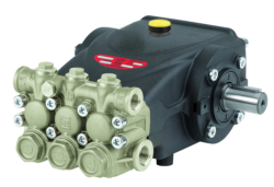
The Interpump E3B2515I pump delivers 15 liters per minute at 250 bar (3,625 psi) with a 7.13 kW motor running at 1,450 rpm. These specifications define the hydraulic envelope within which all piping must operate. The pump weighs 9.5 kg with compact dimensions of 265 mm, allowing installation in space-constrained equipment rooms common in retrofit scenarios.
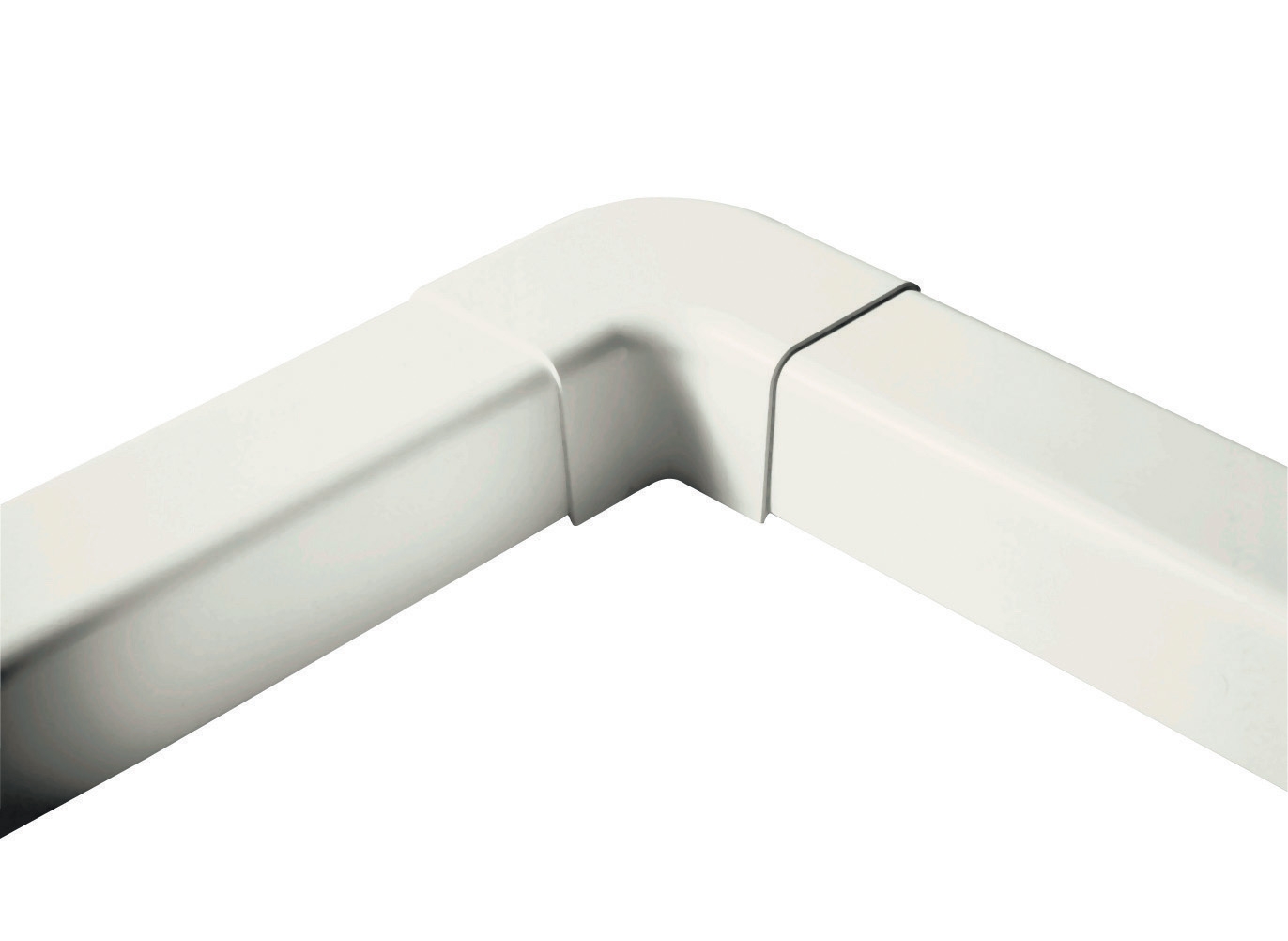
Paired with this pump, the CBM flat elbow 90° (60mm) represents a critical component selection. In HVAC systems, the flat elbow design minimizes turbulence compared to traditional radius elbows, reducing friction loss by approximately 15-20% depending on flow velocity. The 60mm dimension accommodates the primary distribution line in mid-sized systems, balancing flow velocity (typically 2-3 m/s in chilled water circuits) with pressure drop constraints.
When selecting multiple Interpump E3B2515 L pump units for larger facilities, contractors must account for parallel or series piping arrangements. Series configurations sum the pressure rise from each pump stage; parallel arrangements divide flow between identical pump units. In either case, elbow design and pipe diameter determine whether the system pressure drop remains within the pump's performance curve—typically a 5-10% safety margin below the pump's maximum rated pressure.
For advanced applications requiring pressure regulation and modulation, the Interpump E3B1515 pump with integrated valve and RS500H gearbox offers factory-matched components that simplify piping design. The integrated valve package pre-calibrates pressure control, reducing the need for field-installed regulators and secondary piping manifolds. This design reduces installation risk in complex retrofit scenarios.
Pressure measurement at key system points requires dedicated instrumentation. The CBM glycerin stainless steel pressure gauge (0-4 bar) provides reliable analog measurement in low-pressure applications, while digital detection devices support electrical safety during commissioning and maintenance procedures.
Real-World Application Scenarios Across Global Markets
Scenario 1: Singapore Industrial Complex Retrofit
A manufacturing facility in Singapore required upgrading its chilled water circulation system to support expanded production capacity. The original system used undersized 40mm piping with traditional radius elbows, resulting in system pressure drop exceeding 2.5 bar at design flow. By replacing the piping with 60mm diameter lines and flat elbow components, friction loss dropped to 0.8 bar—well within the Interpump pump's performance envelope. The retrofit also reduced annual energy consumption by 18%, recovering the investment in new piping within three years.
Scenario 2: Multi-Building European Campus System
A university campus across three buildings required a centralized HVAC system with remote pump stations feeding distributed chilled water loops. The design challenge involved managing pressure synchronization across 400 meters of primary distribution piping with multiple elevation changes. By specifying identical Interpump pump units at each station and carefully sizing elbows and reducers using friction loss calculations, the design team maintained consistent supply pressure within ±0.3 bar across all three buildings—far exceeding the ±0.5 bar tolerance typical for comfort conditioning applications.
Scenario 3: Data Center Cooling Application
A hyperscale data center in North America required redundant cooling circuits with failover capability. Each circuit used paired Interpump pumps in series configuration, with flat elbows minimizing pressure drop through the high-density cooling unit manifolds. The system maintained 250 bar operating pressure across all circuits, enabling efficient heat rejection even during peak demand periods when facility chiller load reached 95% capacity.
Comparison Table: Pump and Piping Component Selection Matrix
| System Parameter | Interpump E3B2515I | Interpump E3B2515 L | Integrated Pump + Valve |
|---|---|---|---|
| Flow Rate | 15 L/min | 15 L/min | 15 L/min |
| Pressure Rating | 250 bar (3,625 psi) | 250 bar (3,625 psi) | 250 bar (3,625 psi) |
| Motor Power | 7.13 kW (9.7 hp) | 7.13 kW (9.7 hp) | 7.13 kW (9.7 hp) |
| Operating Speed | 1,450 rpm | 1,450 rpm | 1,450 rpm + gearbox |
| Weight | 9.5 kg | 9.5 kg | 11.2 kg (with gearbox) |
| Recommended Piping Diameter | 50-63 mm | 50-63 mm | 50-63 mm |
| Elbow Friction Factor | Flat: ~0.15 bar per 90° | Flat: ~0.15 bar per 90° | Flat: ~0.15 bar per 90° |
| Typical System Margin | 8-12% pressure reserve | 8-12% pressure reserve | Integrated control maintains margin |
| Best Application | Standard HVAC circuits | Standard HVAC circuits | Complex retrofit, redundancy |
Selecting Complementary Piping Components: A Practical Framework
When specifying industrial pump systems for global HVAC applications, follow this data-driven selection process:
Step 1: Calculate System Head
Determine the total pressure drop required across all piping, fittings, and terminal equipment. Use friction loss charts based on actual flow velocity and pipe material. For a system requiring 15 L/min through 60mm diameter piping, expect approximately 0.6-0.8 bar friction loss per 100 meters of straight pipe, plus additional loss through elbows and valves.
Step 2: Select Pump Performance Curve
Choose a pump whose performance curve intersects your calculated system head at the desired flow rate. The Interpump units specified here deliver full 15 L/min flow across a wide pressure range (50-250 bar), making them suitable for most HVAC applications.
Step 3: Optimize Piping Geometry
Specify flat elbow components rather than traditional radius elbows to minimize friction losses. The CBM 60mm flat elbow reduces pressure drop by 15-20% compared to standard elbows, translating directly to energy savings and extended pump service life.
Step 4: Install Pressure Monitoring
Commission systems with analog or digital pressure gauges at pump discharge and system return points. Pressure differential should remain stable across operating hours, indicating proper component sizing and system balance.
Step 5: Plan for Global Compliance
Verify that selected components meet regional standards: CE marking for Europe, ANSI/ASME for North America, and equivalent pressure equipment directives for Asia-Pacific installations. Material certifications and pressure testing documentation should accompany all shipments.
3G Electric's industrial equipment specialists maintain inventory across all specified components and can support site-specific engineering calculations. Whether you're designing a new HVAC system for a Singapore manufacturing facility or retrofitting cooling infrastructure at a European campus, our technical team can help you balance pump selection with complementary piping components to achieve optimal performance and lifecycle cost.
Contact 3G Electric today to discuss your industrial HVAC system requirements. Our engineers will help you evaluate pump and piping options specific to your facility's flow demands, pressure requirements, and global compliance obligations. With 30+ years serving industrial customers worldwide, we provide both equipment and expertise to ensure your HVAC systems operate at peak efficiency.