Understanding High-Pressure Component Integration in Industry Applications
High-pressure systems are the backbone of modern industrial applications—from agricultural spraying operations to precision cooling systems and industrial cleaning. When pressure components fail or underperform, production losses mount quickly. With over 35 years of experience distributing industrial equipment globally, 3G Electric has observed that most pressure-related failures stem not from single component defects, but from improper integration between couplings, nozzles, reduction fittings, and mounting infrastructure.
This troubleshooting guide focuses on the interconnected relationship between pressure reduction couplings, flat jet nozzles, and wall-mounted support systems. When these components work together correctly, your system maintains optimal pressure delivery and spray patterns. When integration fails, you lose pressure, experience inconsistent spray coverage, and face unexpected downtime.
Diagnosing Pressure Loss Across Coupling-to-Nozzle Integration
Pressure loss between your main pressure line and the nozzle outlet is the most frequent complaint maintenance teams encounter. The diagnostic challenge lies in isolating whether loss occurs at the coupling interface, within the reduction fitting, or at the nozzle connection point.
Step 1: Establish Baseline Pressure Reading
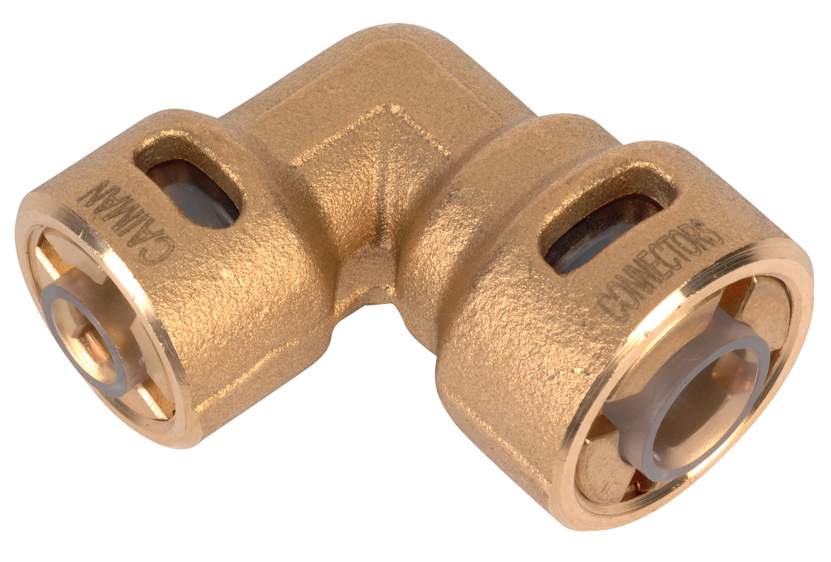
Before troubleshooting begins, measure pressure at three critical points: at the pump discharge, immediately after the pressure reduction coupling 90° pressure reduction 1/4*3/8, and at the nozzle inlet. Document all readings under identical operating conditions (engine RPM, throttle position, temperature). Most pressure loss exceeds 15% of system pressure—a diagnostic red flag.
Step 2: Inspect Coupling Face Seals
The 90° pressure reduction coupling uses face-seal technology that deteriorates when exposed to contaminants or thermal cycling. Disconnect the coupling at both connection points (do this safely with system depressurized). Inspect the male and female sealing surfaces using magnification—scratches, corrosion spots, or discoloration indicate seal degradation.
Common causes of coupling seal failure:
- Dust or metal particulates trapped during connection
- Thermal expansion mismatches (especially in outdoor equipment exposed to temperature swings)
- Over-tightening that distorts the sealing surfaces
- Use of incompatible thread sealants that degrade the seal material
Step 3: Verify Reduction Ratio Specification
The 1/4" to 3/8" size reduction represents a specific flow-to-pressure relationship. If your application requires pressure reduction from 150 bar to 80 bar, a single 90° reduction coupling may not deliver the pressure drop your system requires. This is particularly common when teams retrofit existing systems without recalculating pressure requirements.
Diagnostic approach: Review your original system design documentation. If pressure specifications don't match the coupling's design ratio, you may need a cascaded reduction strategy—using two reduction points instead of one—or upgrading to a higher-capacity coupling designed for your pressure range.
Nozzle Performance Verification and Angle/Index Selection Issues
Three high-pressure nozzle variants are commonly integrated into industrial systems: the flat jet nozzle HP index 25 at 15° angle, the flat jet nozzle HP index 055 at 15° angle, and the flat jet nozzle HP index 50 at 40° angle. Maintenance teams often overlook that each index number and angle specification serves distinct application requirements.
Index Number Explained
The index number (25, 055, 50) refers to the nozzle's flow rate capacity at rated pressure. An index 055 nozzle delivers roughly one-third the flow of an index 25, and an index 50 delivers double the flow of index 25. Selecting the wrong index for your application creates two problems: insufficient flow (causing slow spray coverage) or excess flow (causing overspray and pressure system strain).
Common Troubleshooting Scenario: Inadequate Spray Coverage
Maintenance teams report that spray coverage areas appear smaller than expected, requiring multiple passes. Before assuming equipment failure, verify you're using the correct nozzle index for your application:
1. Check the installed nozzle marking. The index number is stamped on the nozzle body. If it doesn't match your design specification, someone performed an improper repair replacement.
2. Measure actual flow rate. With system running at rated pressure, capture nozzle output into a calibrated container for 60 seconds. Compare measured flow against the nozzle's published specifications. A 10%+ variance indicates internal blockage or wear.
3. Inspect the nozzle orifice under magnification without disassembly first. Look for mineral buildup, corrosion, or debris. If water quality is poor or fuel contains contaminants, the small orifice plugs easily.
Spray Angle Verification
The 15° angle specification (on both index 25 and index 055 models) differs fundamentally from the 40° angle of the index 50 model. A 15° spray produces a narrow, concentrated stream suitable for direct impact cleaning. A 40° angle spreads flow across a wider area, ideal for general coverage applications.
If your spray pattern appears wrong:
- Verify angle matches your application requirement
- Inspect the nozzle tip for damage or deformation that would alter the angle
- Confirm the nozzle is fully seated in its connection (a partially installed nozzle creates unpredictable spray patterns)
Before replacing a nozzle, attempt this cleaning sequence:
1. Remove the nozzle from the system
2. Soak in appropriate solvent (water for water-system deposits, fuel-based solvent for fuel residue) for 2-4 hours
3. Use a plastic brush to gently clean external surfaces
4. DO NOT use metal needles or wires that damage precision orifices
5. Rinse thoroughly and allow to air dry
6. Reinstall and test at rated pressure
If cleaning doesn't restore performance, replacement is necessary.
Wall Bracket Installation and System Stability Issues
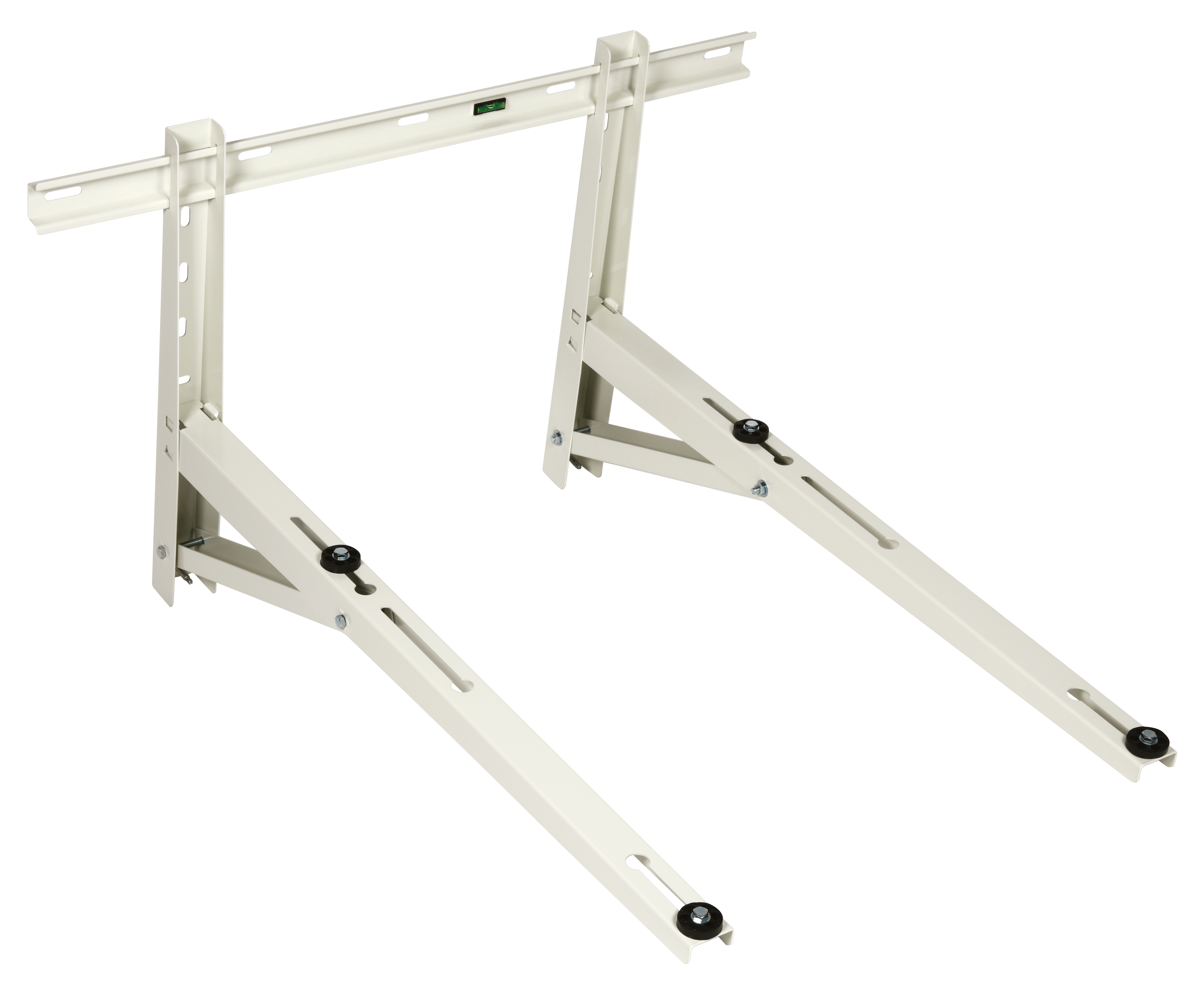
The wall bracket 1000 serves more than aesthetic purposes—it provides structural support that affects pressure stability and prevents vibration-induced coupling failures. Poor bracket installation is a frequently overlooked root cause of pressure fluctuations and unexpected component disconnections.
Installation Verification Checklist
Before assuming pressure components are faulty, verify bracket installation quality:
Wall Surface Assessment
- Confirm the mounting wall is concrete, reinforced wood, or metal—not drywall alone
- Inspect for signs of previous damage, cracks, or water damage that compromise structural integrity
- Verify the wall surface is flat (use a straightedge across mounting points)
- On masonry surfaces, confirm fasteners are expanding anchor types rated for your load
- The bracket must position the pressure line horizontally or with minimal slope
- Hanging systems under their own weight create stress on coupling connections
- Measure the distance between the bracket anchor points and the actual coupling center—misalignment creates torque on connections
- The 1000-series bracket is rated for specific weight loads when properly installed
- Calculate your actual load: pressure line weight (full length) + coupling weight + nozzle assembly weight + pressure-generated forces
- If load exceeds bracket rating, implement a secondary support point or upgrade bracket capacity
- High-pressure systems generate vibration, especially when solenoid valves cycle or pump displacement adjusts
- Ensure bracket fasteners are torqued to specification and locking washers are installed
- Check fasteners every 100 operating hours during the first month—vibration settling loosens new installations
If the pressure line shows movement or the coupling appears to shift when the system pressurizes:
1. Run the system and observe the coupling area in safe operating condition
2. Mark the coupling position with paint or tape on the wall
3. Pressurize the system fully and observe whether the coupling moves
4. If movement exceeds 3mm, the bracket is undersized or fasteners are insufficient
5. In this condition, vibration amplifies coupling wear and seal damage accelerates
Integration Testing and System Stabilization Procedures
Once individual components pass diagnostic verification, the integrated system must be tested as a complete unit under load.
Pre-Operation System Flush
Before running your system after any component replacement or maintenance:
1. Remove all nozzles from the system
2. Run the system at 50% of rated pressure for 5 minutes to flush air and loose debris
3. Inspect fluid exiting the open nozzle ports—it should be clear with no visible particulates
4. If fluid appears cloudy or contains visible particles, continue flushing until clear
5. Reinstall nozzles only after flush fluid is confirmed clean
This step prevents new components from being immediately damaged by contamination in system lines.
Pressure Stability Verification
Under normal operation, pressure readings should remain stable within ±5% of set point. If pressure fluctuates beyond this range:
1. Document the fluctuation pattern: Does pressure spike/drop at regular intervals, randomly, or under specific conditions (like when another valve opens)?
2. Isolate system sections: Close valves to disconnect portions of the system one at a time. If pressure stabilizes when a section is isolated, the problem exists in that isolated section.
3. Check for loose connections: Pressure fluctuations often signal a coupling or fitting that's not fully seated. Tighten all connections incrementally (¼ turn at a time) and retest.
4. Verify relief valve function: If pressure exceeds set point, your relief valve may be sticking. This should be tested by a qualified technician with proper pressure-relief testing equipment.
Temperature Monitoring During Extended Operation
System components expand when temperature rises. Monitor component temperatures at 30-minute intervals during first operation:
- Coupling bodies should remain warm to touch but not hot (below 60°C ideal)
- Nozzles may run warmer, but temperature-induced spray pattern changes indicate potential seal degradation
- Brackets should show minimal temperature increase (they dissipate heat away from pressure lines)
If components run hotter than expected, investigate pressure losses (which generate heat through resistance) and verify that support brackets aren't restricting fluid flow or creating dead zones where heat accumulates.
Maintenance and Preventive Care for Global Applications
Different global regions present unique challenges. 3G Electric's 35+ years serving international industrial markets has revealed region-specific maintenance priorities:
High-Dust Environments (agricultural regions, desert climates):
- Increase nozzle inspection frequency to weekly
- Install secondary strainers before pressure reduction couplings
- Clean bracket fasteners monthly to prevent dust-induced corrosion
- Inspect coupling seals monthly for corrosion
- Use corrosion-resistant fasteners on wall brackets
- Apply protective coatings to metal bracket surfaces quarterly
- Verify coupling seal material compatibility with temperature swings
- Check nozzle spray patterns before and after temperature cycling
- Increase bracket fastener torque checks to twice-monthly intervals
- Inspect bracket fasteners weekly during the first month of operation
- Consider reinforced bracket installation with additional anchor points
- Monitor coupling for micro-movement that precedes seal failure
Quick Reference: Component Replacement Decision Matrix
Use this matrix when deciding whether to repair/clean or replace components:
Replace the Pressure Coupling 90° reduction coupling immediately if:
- Seal surfaces show scratches deeper than light surface marks
- Pressure loss exceeds 20% from coupling location
- Coupling has been disconnected more than 10 times (seal face fatigue)
- System operates above 150°C (thermal seal degradation)
- Flow rate deviates more than 10% from specification after cleaning
- Spray pattern becomes distorted or uneven
- Nozzle has been in service for more than 1000 operating hours without replacement
- Visual inspection reveals cracks or permanent deformation
- Fasteners consistently loosen despite lock washer installation
- Bracket shows visible bending or deformation
- Pressure line experiences movement exceeding 3mm under full pressure
- Load calculations exceed bracket rated capacity
With proper diagnosis and timely component replacement guided by this framework, your maintenance team will minimize unplanned downtime while extending component service life across your global industrial operations.