Gas Valves & Regulation: Selection, Sizing & System Integration for Singapore Operations
Gas Valves & Regulation represent one of the most critical control points in industrial fluid and gas systems, yet proper selection and sizing remains inconsistent across many Singapore-based operations. With over 35 years of experience distributing industrial equipment across Southeast Asia, 3G Electric has observed that most performance failures stem not from component defects, but from incorrect valve selection and undersized regulation systems. This technical guide provides actionable frameworks for sizing gas valves, integrating them into existing systems, and validating performance before commissioning.
Understanding Valve Selection Fundamentals
Gas valve selection begins with understanding your system's fundamental operating parameters. Unlike mechanical switches, gas valves operate within narrow pressure and flow windows that directly impact system reliability and safety. The selection process requires simultaneous evaluation of five key variables: maximum operating pressure (MOP), steady-state flow rate (Qn), inlet and outlet pressures, fluid media characteristics, and environmental conditions specific to your facility.
Maximum Operating Pressure (MOP) Determination
Your valve's MOP rating must exceed your system's relief setting by a minimum safety margin. In Singapore's tropical industrial environment, many operators underestimate pressure spikes during startup sequences or emergency shutdown conditions. Best practice requires selecting a valve with MOP rated at 120-150% of your system's maximum relief pressure. For example, if your hydraulic circuit relieves at 280 bar, specify valves rated for minimum 336-420 bar MOP. This provides buffer capacity during transient pressure events common in mobile equipment, press systems, and pump-driven applications.
The Pratissoli Automatic Press Regulator H288 exemplifies properly-rated regulation equipment for high-pressure industrial hydraulic applications. With its 280 bar maximum pressure capacity and 20 L/min flow rating, this regulator handles typical industrial press circuits while maintaining precise outlet pressure adjustment. Its 85°C temperature rating accommodates Singapore's ambient conditions and normal system operating temperatures without performance degradation.
Flow Rate Calculations and Margin Requirements
Flow rate sizing demands greater precision than many procurement processes allow. System flow (Qn) should be calculated based on actuator speed requirements and cycle times, not estimated from similar competitor equipment. A common error occurs when specifying regulation equipment based on pump displacement alone. Your actual circuit flow may be 60-70% of pump output due to load-holding requirements, meter-out restrictions, and proportional valve settings.
Calculate required valve flow as: Qn = (Actuator displacement × Stroke speed) + (Secondary circuit flow) + (Pilot signal flow). Then specify your valve for 1.25-1.5× calculated flow to ensure stable regulation across the full pressure range. Undersized valves operate near their maximum capacity, causing pressure oscillation, temperature rise, and accelerated wear. Oversized valves sacrifice precision and create stability issues in proportional control systems.
Pressure Regulation System Design Integration
Regulation equipment never operates in isolation. Each valve functions within a pressure control hierarchy that includes pilot supplies, feedback circuits, and relief protection. Improper integration between components creates cascade failures that operators misattribute to individual valve defects.
Pilot Supply Circuit Design
Pilot-operated regulation systems require dedicated pilot supplies separate from main circuit pressures. Many Singapore facilities operate hybrid systems combining direct-acting and pilot-operated valves, creating pressure conflicts at critical control points. Your pilot supply pressure must remain stable (± 5 bar maximum drift) regardless of main circuit load changes. This typically requires a dedicated, filtered pilot pump or pressure-reducing valve maintaining 20-30 bar above the main system's normal operating pressure.
The Pratissoli Pilotflex 120 High Pressure Hose provides the necessary flow capacity and pressure rating for sophisticated pilot circuits. Pilotflex technology maintains consistent pressure delivery while absorbing pressure transients that would otherwise destabilize sensitive regulation valves. For facilities upgrading legacy systems, this product enables safer integration of modern proportional and directional control equipment without requiring complete circuit redesign.
Feedback and Load-Sensing Configuration
Load-sensing regulation systems adjust main valve opening based on actual load pressure rather than fixed setpoints. This approach reduces heat generation by 30-40% compared to fixed-relief designs and enables significant energy cost reduction across industrial operations. However, load-sensing systems demand precise feedback circuit design, as signal delays or filtering errors cause oscillation or instability.
In your load-sensing design, calculate feedback signal lag as: Time lag (ms) = Feedback line volume (cm³) / Pump flow (cm³/s). Feedback lines longer than 3 meters require inline accumulators (0.5-1.0 liter volume) to dampen pressure oscillation. Restricted feedback lines (less than 50 cm² cross-section) must be evaluated for signal distortion—pilot signals require minimum 100 cm² to maintain system stability. Many Singapore plants installed in the 1990s-2000s use undersized feedback plumbing that creates mysterious system oscillation. Upgrading feedback circuits typically costs 15-20% of new valve investment but eliminates decades of troubleshooting.
Specification Matching and Valve Selection Worksheet
Successful valve selection requires systematic specification matching rather than opportunistic purchasing. This section provides a practical worksheet framework used by 3G Electric's technical team across 35+ years of Southeast Asian industrial operations.
System Parameters Documentation
Before engaging suppliers or selecting components, compile the following system documentation:
- Circuit Configuration: Identify whether your system operates as fixed-displacement pump with fixed relief, variable-displacement pump with pressure compensation, load-sensing pump with proportional valve, or hybrid configuration combining multiple control methods.
- Fluid Media: Confirm ISO fluid classification (ISO VG 32/46/68 for hydraulics), biodegradable status, and viscosity index. High-temperature fluids (ISO VG 22) common in Singapore manufacturing require valves rated for lower viscosity response and thermal stability.
- System Cleanliness: Document current filtration level (ISO 4406 code) and planned maintenance intervals. Valves selected for ISO 17/15/12 systems require different spool clearances than 20/18/15 circuits.
- Pressure Profile: Map pressure values across key system points during normal operation and emergency shutdown. Use pressure chart recorders to capture transient spikes during load release events.
- Environmental Conditions: Document facility ambient temperature range, humidity (critical in Singapore's 70-90% humidity), vibration environment (if equipment operates near presses or impact machinery), and electrical supply characteristics (three-phase AC availability, power factor correction, harmonics).
Once system parameters are documented, select regulation equipment using these decision criteria:
1. Relief Valve Selection: For systems with fixed pump displacement and variable load, direct-acting relief valves (simplest design) suit applications below 50 L/min and 210 bar. Larger systems or high-flow requirements demand pilot-operated relief valves with external drain capability. Pilot-operated designs generate 40-60% less heat and enable tighter pressure control (±5 bar vs ±10 bar for direct-acting).
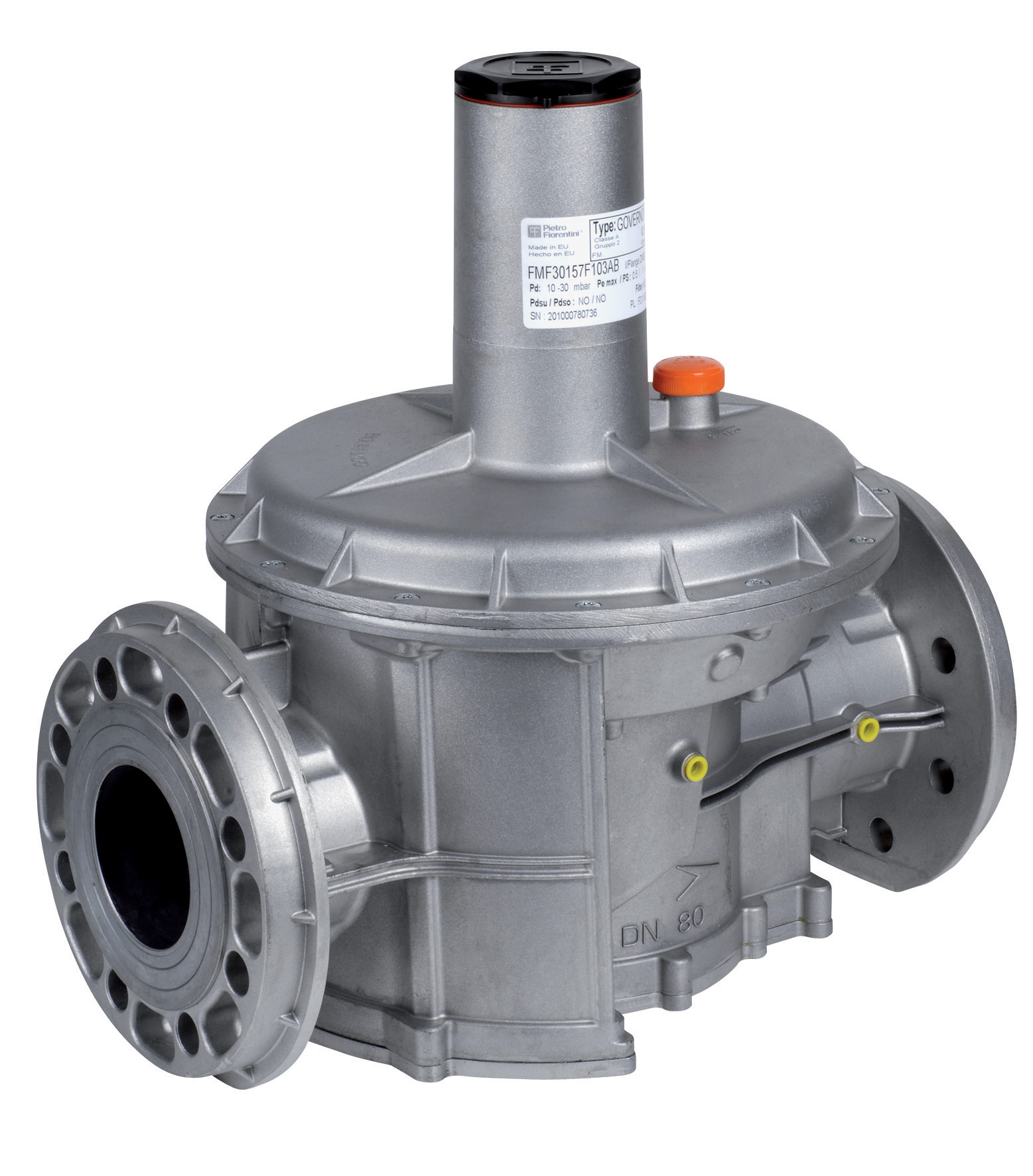
2. Pressure Reducing Valve Selection: Secondary circuits requiring lower pressures than main system demand pressure-reducing valves. Direct-acting reducers work well for continuous, light-load applications. Pilot-operated reducers suit circuits with variable load or frequent pressure changes. The FAG Pressure Regulator with Flanges DN40 demonstrates modern pressure reduction design for specialized applications, offering outlet pressure adjustment from 5 to 300 mbar with DN40 flange interfaces. This equipment suits low-pressure applications, instrumentation circuits, and specialty control systems requiring precise, stable outlet pressure regardless of inlet fluctuation.
3. Proportional Valve Integration: Modern Singapore manufacturing increasingly adopts proportional and directional control valves for energy efficiency and process precision. These valves require additional consideration for electrical power supply, signal quality, and feedback circuit design. Proportional equipment generates electromagnetic interference (EMI) that affects nearby sensors and control systems—spatial separation and cable routing discipline become critical design elements.
Flow Capacity Validation
After selecting specific valve models, validate flow capacity across your expected operating range. Request flow curve data from equipment suppliers showing pressure drop (ΔP) vs. flow rate (Q) across the valve. Compare actual system pressure drops to specification data—field performance differs from lab conditions due to fluid temperature variations, contamination levels, and component wear. Conservative practice suggests accepting pressure drops 10-15% higher than specification data to account for real-world degradation over equipment lifetime.
For complex systems, consider small-scale bench testing before full production commissioning. A test circuit using Pratissoli PUMP SRS65 1800 VER V 400V-AC enables validation of valve sizing, pressure regulation response, and thermal behavior under realistic load conditions. This equipment delivers 6 L/min at 170 bar maximum pressure in a compact 0.42 kg form factor—ideal for test circuits, mobile applications, or retrofit installations where space constraints limit equipment size. Bench testing investment (typically 5-8% of total system cost) prevents commissioning failures that generate 10-15x greater downtime costs.
Singapore-Specific Compliance and Installation Considerations
Singapore's regulatory environment and tropical conditions create unique requirements for gas valve installation and operation. The Ministry of Manpower (MOM) Machinery Safety Regulations and Professional Engineers Board (PEB) technical guidelines establish mandatory standards for pressure equipment exceeding 25 bar. Additionally, Singapore's maritime and offshore industries (which drive significant industrial equipment demand) follow IMCA and DNV-GL certification requirements.
Pressure Equipment Directive Compliance
All pressure equipment rated above 25 bar in Singapore must carry PED (Pressure Equipment Directive) certification or equivalent SAE/ASME documentation. Valves imported from European suppliers typically carry CE marking and PED documentation. Non-CE marked equipment (particularly from South Asian suppliers) often lacks documentation, creating liability exposure and potential facility closure risk during regulatory inspection. 3G Electric maintains full compliance documentation for all pressure equipment, eliminating procurement risk for regulated facilities.
Thermal Management in Tropical Conditions
Singapore's ambient temperatures (24-32°C year-round) combined with high humidity (70-90%) create unique challenges for regulation system thermal stability. Heat generation in regulation valves increases valve temperature 15-25°C above ambient during full-flow operation. In air-conditioned facilities, this temperature differential can exceed 35°C, causing viscosity changes and pressure oscillation. Best practice requires:
- Installing inline coolers for systems generating >5 kW heat during normal operation
- Specifying valves with extended temperature operating range (0-85°C minimum)
- Planning for seasonal viscosity adjustments during pre-monsoon humidity increases
- Using biodegradable fluids (HETG or HEES classification) which tolerate wider temperature ranges than mineral-based hydraulics
High-pressure connections between valves require certified hoses meeting SAE 100R13 or EN 856 standards. Many Singapore facilities continue using older EN 853 hoses, which generate higher pressure drop and generate excessive heat in regulation circuits. Upgrading to modern EN 286 or SAE 100R2AT hose reduces pressure drop by 30-40% and improves system stability. The Pratissoli Long Life High Pressure Sewer Cleaning Hose ZT06B1000353 represents Italian-engineered quality standard for demanding high-pressure applications, offering complete fitted hose assemblies that eliminate field assembly quality variability.
Electrical Integration for Solenoid and Proportional Valves
Electrical supply quality directly impacts proportional and solenoid valve reliability. Singapore's electrical infrastructure generally provides stable three-phase AC at 400V ±10% with total harmonic distortion (THD) below 5%. However, facilities with large drives, welding equipment, or induction furnaces often experience harmonic distortion exceeding 8%, causing proportional valve coil failures and erratic control behavior. Specify proportional equipment for your actual site electrical conditions rather than nominal values. If THD exceeds 5%, invest in harmonic filters (typically 2-3% of electrical installation cost) to protect sensitive control equipment.
Commissioning and Performance Validation Protocol
Proper commissioning transforms component selections into reliable operating systems. Many Singapore facilities skip systematic commissioning, resulting in performance issues attributed to equipment quality rather than installation or configuration errors.
Pre-Commissioning System Flush
Flush all circuits with clean fluid (ISO 4406 16/14/11 minimum cleanliness) before introducing regulation equipment. Circulate fluid through the system for minimum 8 hours with all valves bypassed (relieved to tank). This removes installation contamination—welding spatter, thread tape, hose abrasive coating, and metal particles from pipe cutting. Inadequate flushing reduces valve lifespan by 60-80% and creates pressure oscillation that persists throughout equipment lifetime.
Regulation Valve Tuning and Setpoint Verification
Once circuits are clean, set relief valve pressure incrementally while monitoring system stability. Begin at 20% below target pressure, then increase in 20 bar increments while observing pressure gauge response. Stable, smooth pressure increase indicates correct pilot circuit design. Oscillating or erratic response suggests pilot supply problems, feedback circuit issues, or proportional valve signal quality problems requiring investigation before proceeding.
Load Testing and Thermal Monitoring
Operating systems under full design load for 4-8 hours reveals problems that remain hidden during light-load operation. Monitor system temperature every 30 minutes during initial load testing. Excessive temperature rise (exceeding 60°C or 10°C above calculated expectations) indicates undersized valves, excessive pressure drop, or load-sensing system instability. Address thermal issues during commissioning rather than attempting field adjustment after production equipment commissioning—thermal problems typically worsen with time as component wear increases pressure drops.
Documentation and Performance Baseline Establishment
Maintain comprehensive commissioning records including final setpoint pressures, response times, temperature profiles, and pressure transient characteristics. These records establish the performance baseline against which future maintenance decisions are evaluated. Without baseline documentation, maintenance teams cannot reliably distinguish between normal operating drift and performance degradation requiring intervention.