Gas Burner Modulation & Control Systems: A Technical Comparison for Global Industrial Operations
Industrial gas burners represent one of the most critical components in modern heating and combustion systems, yet the relationship between burner hardware and its control systems often confuses maintenance teams and service engineers. The choice between modulating (variable-output) and fixed-output burners directly influences control system selection, operational efficiency, and long-term maintenance complexity. This article explores the technical architecture of modern gas burners and their associated control systems, helping you understand how modulation capabilities, safety relays, and combustion management work together—and why these distinctions matter for your facility's performance globally.
Understanding Burner Modulation Architecture in Industrial Applications
Modulating gas burners differ fundamentally from fixed-output units in how they deliver fuel and respond to changing load demands. A modulating burner uses a PID (Proportional-Integral-Derivative) control loop to continuously adjust the flame intensity based on real-time feedback from temperature sensors or pressure transducers. This differs sharply from on-off burners, which operate at full capacity or remain idle—producing significant thermal swings and energy waste.
The mechanical foundation of modulating burners involves several key components: a die-cast aluminum body for durability and heat dissipation, a high-pressure fan system that maintains precise air delivery across the entire modulation range, and a precision combustion head engineered for stability at both minimum and maximum loads. The combustion head includes adjustment mechanisms that fine-tune the air-fuel ratio at each modulation level, maintaining high efficiency and preventing incomplete combustion.
When a modulating burner operates at partial load—say 40% of its rated capacity—the system reduces both fuel flow and air supply proportionally. This contrasts with fixed-output burners, which would cycle on and off, creating overshooting and undershooting of the target temperature. For industrial processes requiring tight temperature control (pharmaceutical production, food processing, steam generation), this continuous modulation delivers measurable advantages: reduced energy consumption, improved product quality, and extended equipment lifespan due to lower thermal stress.
The control architecture supporting modulation typically includes an electronic relay that processes signals from multiple sensors. These relays perform several functions: safety interlocking (ensuring the system cannot fire without proper air pressure and fuel pressure conditions), flame supervision (confirming combustion is occurring), and modulation signal generation (sending proportional voltage or current commands to the fuel valve and air damper). Understanding this layered safety-and-control architecture is essential for proper commissioning, troubleshooting, and maintenance.
Technical Specifications of Modern Modulating Burners and Their Control Relays
The FBR Burner GAS X5/MF TL EL VC LPG represents a current-generation modulating gas burner suitable for applications across multiple industrial sectors globally. This unit features a 370W fan motor capable of delivering high-pressure combustion air, with a maximum power output of 349 kW and a minimum output of 69.8 kW—yielding a turn-down ratio of approximately 5:1. This range allows operators to maintain stable combustion across a wide load spectrum without excessive cycling.
The burner's die-cast aluminum construction provides excellent thermal properties and corrosion resistance in industrial environments. Its compact dimensions and rationalized component layout simplify installation in space-constrained equipment like boilers and furnaces. The unit achieves IP 40 electrical protection, suitable for workshops and industrial spaces where dust and occasional water spray are present. Critically, this burner operates on natural gas and LPG across fuel categories I2R, I2H, I2L, I2E, I2E+, and I3 variants—ensuring compatibility with diverse regional fuel supplies. The minimum pressure requirement of 27 mbar for natural gas and 33 mbar for LPG reflects modern burner efficiency and safety standards.
The control system architecture supporting modulating burners involves specialized electronic relays. The CBM Relay SM 592.2 TW1.5/TS10 exemplifies this category—an electronic control system designed specifically for atmospheric and fan-assisted burners in intermittent operation mode. This relay incorporates non-volatile lock-out functionality, meaning that if unsafe conditions occur (loss of flame, air pressure failure, fuel pressure deviation), the system enters a safe state that requires manual intervention to reset. This design prevents hazardous automatic restart attempts.
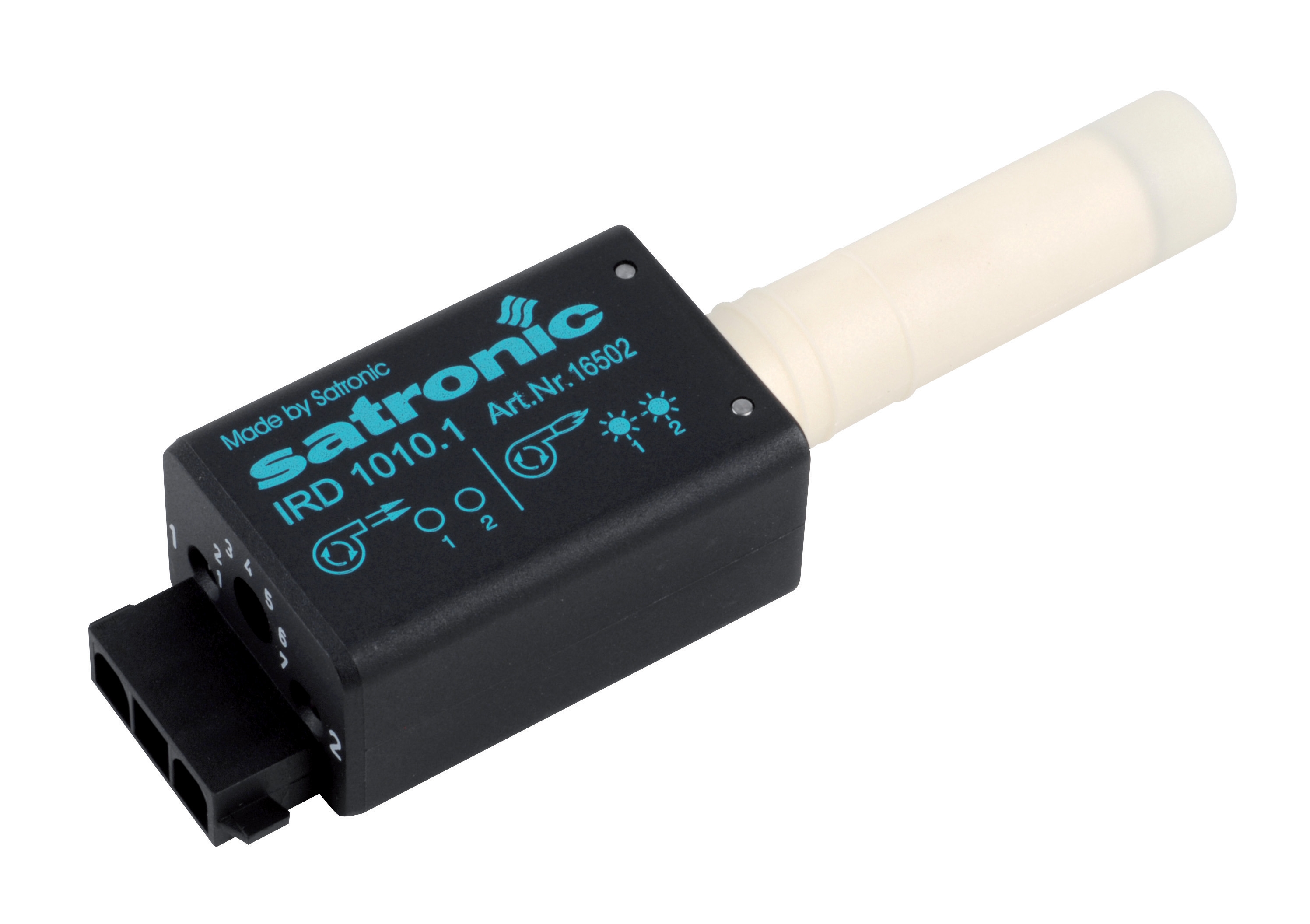
For applications requiring infrared flame detection—particularly in installations where light-based detection may be compromised by ambient radiation—the CBM IRD 1010 blue cell provides robust flame supervision. This infrared detector monitors the presence of flame by detecting thermal radiation in the infrared spectrum, offering superior rejection of ambient light sources compared to photoresistive sensors. The IRD 1010 connects directly to safety control relays, providing continuous flame presence confirmation throughout the combustion cycle.
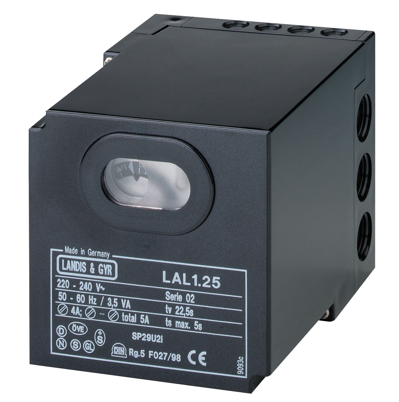
The CBM Relay LAL 2.14 serves a different application segment—safety control systems for oil burners with integrated air pressure monitoring and controlled air damper operation. While optimized for oil combustion, its architecture illustrates the modular nature of modern burner control: separate flame detection (via photometric resistance or blue cell sensors), pressure supervision, and sequencing logic work together to create a complete safety management system.
Real-World Application Scenarios: When Modulation Matters
Consider a steam generation facility in Southeast Asia serving a textile production plant with highly variable steam demand. During peak production hours, the boiler may need to generate 300 kW of heat; during maintenance cycles, demand drops to 100 kW. With a fixed-output burner, the system would cycle on and off approximately every 3-5 minutes, causing pressure oscillations of ±5-10 bar around the setpoint. This cycling stresses boiler tubes, accelerates scale formation in steam lines, and wastes fuel through repeated ignition sequences.
The same facility equipped with a modulating gas burner (such as the FBR GAS X5 series) would maintain a steady modulation profile, adjusting output smoothly from 69.8 kW to 349 kW based on real-time steam demand. The electronic control relay continuously monitors pressure, adjusting the PID algorithm to maintain ±2 bar stability. Over a typical year of operation, this reduces fuel consumption by 8-15% compared to fixed-output cycling, extends boiler component life by 3-5 years, and improves steam quality consistency for downstream processes.
In a pharmaceutical manufacturing context where precise temperature control within ±1°C is mandatory, modulating systems become non-negotiable. A reaction vessel requiring exothermic temperature management cannot tolerate the overshooting and undershooting inherent in on-off burner operation. The continuous adjustment enabled by modulating burners and their associated control systems keeps reaction temperatures stable, reducing batch failures and improving pharmaceutical product consistency—directly impacting regulatory compliance and profitability.
Technical Comparison: Modulating Burners vs. Control System Architecture
| Technical Parameter | Modulating Burner (FBR GAS X5 Series) | Fixed-Output Burner |
|---|---|---|
| Output Range (kW) | 69.8–349 kW (5:1 turn-down) | Single fixed capacity; no modulation |
| Control Type | PID electronic modulation + relay (SM 592.2, LAL 2.14) | Simple on-off sequencer |
| Load Stability | ±2–3% of setpoint | ±5–10% cycling overshoot/undershoot |
| Fuel Consumption (Annual) | Baseline (8–15% savings vs. fixed) | 100% baseline (reference point) |
| Flame Detection Technology | Infrared (IRD 1010) or photoresistive sensor | Photoresistive or UV sensor |
| Electrical Protection | IP 40 (industrial dust/moisture resistant) | IP 40 typical |
| Minimum Operating Pressure (Natural Gas) | 27 mbar (enables low-pressure networks) | Typically 30–40 mbar |
| Commissioning Complexity | Requires PID tuning + sensor calibration | Simple pressure switch setup |
| Typical ROI Period (Global Average) | 2–3 years via fuel savings | Lower capital cost; higher operating cost |
Selecting the Right Control System for Your Burner Architecture
The selection between different control relay architectures depends on three primary factors: fuel type (gas vs. oil), burner configuration (atmospheric vs. forced-draught), and operational mode (intermittent vs. continuous). For gas burners operating in intermittent mode—the most common industrial scenario globally—electronic relays like the CBM SM 592.2 provide integrated safety sequencing, air pressure monitoring, and modulation signal generation in a single compact unit.
When retrofitting existing equipment or upgrading control systems, the CBM Base for GE 733 mounting system provides standardized mechanical and electrical interfaces, allowing modular relay replacement without extensive rewiring. This modular design philosophy—where flame detection, safety logic, and modulation functions connect via standard connector patterns—reduces downtime during maintenance and enables rapid component substitution with compatible alternatives.
Maintenance teams should verify that selected control systems match the specific burner modulation capabilities. A fully modulating burner like the FBR GAS X5 series requires a proportional control signal (0–10V or 4–20mA) from the relay to operate at partial loads. If paired with simple on-off sequencing logic, the burner would operate at full capacity only, defeating its modulation advantages and returning to the cycling inefficiency of traditional burners.
Maintenance and Commissioning Considerations for Modulating Systems
Modulating burner systems demand more rigorous commissioning than fixed-output units. The combustion head air-fuel adjustment must be optimized across the full modulation range—not just at maximum load. Service engineers should perform combustion analysis (measuring O₂, CO, and combustion efficiency) at minimum (69.8 kW), mid-range (approximately 200 kW), and maximum (349 kW) loads to verify stable, efficient combustion throughout the operating envelope.
Electronic control relays require periodic testing of safety functions: air pressure interlock (verify burner cannot fire without adequate fan pressure), flame detection timeout (confirm relay shuts down burner if flame is lost), and modulation signal response (confirm smooth adjustment from minimum to maximum output). Annual inspection of flame detection sensors—whether infrared (IRD 1010 blue cell) or photoresistive types—ensures reliable flame supervision and prevents nuisance shutdowns caused by sensor fouling or optical degradation.
Documentation becomes critical. Maintenance teams should maintain records of commissioning setpoints (air pressure threshold, modulation range calibration, PID tuning parameters), combustion analysis results at each load point, and any adjustments made during operation. This documentation accelerates troubleshooting when issues arise and provides baseline data for comparing performance across seasons or shifts.
Conclusion: Making the Modulation Decision for Your Facility
The transition from fixed-output to modulating gas burners represents a significant operational investment, but the rewards—reduced fuel consumption, improved product consistency, extended equipment life—justify the expense for facilities with variable thermal loads or strict temperature control requirements. Modern burners like the FBR GAS X5 series, paired with electronic control relays and infrared flame detection systems, create a reliable, efficient combustion platform suitable for demanding industrial applications across the globe.
Your facility's specific requirements—fuel type, load profile, temperature tolerance, and available capital—should drive this decision. If you operate in environments with highly variable demand, pharmaceutical or food processing applications requiring tight control, or aging equipment consuming excessive fuel, modulating systems merit serious evaluation. If your operation involves consistent, predictable loads with minimal variation, fixed-output burners with simple controls may remain the most economical choice.
The technical specifications provided here offer a foundation for informed decision-making, but every facility presents unique challenges. Explore 3G Electric's complete burner and control system catalog, or review available burner control options for your specific application. For personalized guidance on selecting the optimal modulation strategy, control system architecture, and flame detection technology for your industrial operation globally, contact the technical specialists at 3G Electric. With nearly 35 years of experience as an experienced industrial equipment distributor, our team understands the combustion requirements of diverse industries and can recommend solutions tailored to your facility's performance and efficiency goals.