Understanding Fuel Delivery System Architecture in Industrial Applications
Fuel delivery systems represent one of the most critical components in industrial heating and combustion applications. A malfunction in any segment—from the expansion tank through the fuel nozzle to the burner assembly—can result in inefficient combustion, equipment shutdown, or safety hazards. With over 35 years of experience serving global industrial clients, 3G Electric has documented that approximately 40% of unplanned downtime in fuel-based heating systems stems from fuel delivery issues rather than burner or ignition failures.
The fuel delivery chain comprises several interdependent systems: the fuel storage and monitoring system, pressure regulation and expansion components, fuel distribution piping, and the atomization nozzle assembly. Each component must function within precise specifications to maintain combustion efficiency. When one element fails, the entire system can cascade into dysfunction. This guide addresses the practical diagnostic procedures maintenance teams can implement to identify root causes quickly and implement targeted solutions.
Diagnosing Nozzle Spray Pattern and Atomization Failures
Identifying Spray Pattern Degradation
The fuel nozzle represents the final critical point where pressurized fuel becomes atomized spray for combustion. Industrial applications rely on precision-engineered nozzles that maintain specific spray angles, cone patterns, and droplet sizes. The CBM Flat jet nozzle HP 1/4"M BSPT index 25 angle 15° and CBM Flat jet nozzle HP 1/4"M BSPT index 055 angle 15° are designed for exacting specifications that must be maintained throughout their operational lifespan.
Maintenance teams should observe these diagnostic indicators when inspecting nozzle performance:
- Asymmetrical spray patterns: One side of the spray cone produces more mist than the other, indicating internal passage erosion or blockage in specific fuel galleries
- Reduced spray cone angle: The spray narrows from the designed 15° angle, suggesting partial internal obstruction from carbon deposits or fuel varnish
- Inconsistent droplet atomization: Visible large droplets mixed with fine mist indicates erosion of internal spray-forming surfaces or cavitation damage
- Flame instability at constant burner settings: Even with stable fuel pressure and air supply, the flame exhibits pulsing or flickering, pointing to atomization inconsistency
Before replacing a nozzle, verify that the problem originates at the nozzle itself rather than upstream supply issues. Perform these sequential tests:
1. Pressure verification: Confirm fuel pressure at the nozzle inlet meets specifications (typically 0.5-2.5 MPa for industrial applications). Use calibrated pressure gauges—do not rely on burner control panel readings alone, as these may reflect system pressure rather than nozzle inlet pressure.
2. Flow rate measurement: Collect fuel spray into a calibrated container for 60 seconds at rated burner firing rate. Compare actual flow against the nozzle's rated flow capacity (marked on the nozzle body). Flow deviation exceeding ±10% from rated specification indicates nozzle replacement is required.
3. Spray visualization test: In a darkened area, observe the spray pattern from multiple angles. Use white cardboard positioned 30-50cm from the nozzle tip to examine spray symmetry. Photograph the pattern for comparison against nozzle specification sheets.
4. Backpressure assessment: If the nozzle exhibits reduced flow but normal inlet pressure, the internal passages may be obstructed. Attempt gentle backflushing with clean fuel (not compressed air, which can damage precision passages). If flow doesn't improve, the nozzle requires replacement.
Common Nozzle Failure Modes and Causes
Understanding why nozzles fail helps maintenance teams prevent recurrence:
- Carbon buildup and deposit accumulation: Incomplete combustion or fuel oxidation deposits carbon inside nozzle passages. This occurs gradually and is visible as darkening spray pattern over weeks of operation.
- Fuel varnish formation: Aged fuel or exposure to elevated temperatures creates gummy deposits that progressively restrict fuel flow. Check fuel tank condition and consider fuel conditioning if varnish is found.
- Water contamination: Fuel absorbs atmospheric moisture, particularly in humid environments. Water creates corrosion inside nozzle galleries and promotes microbial growth in fuel tanks. If water is present, the fuel tank requires drainage and fuel replacement.
- Mechanical erosion: High-velocity fuel jets erode internal spray-forming surfaces over extended operation, particularly if the nozzle operates at pressures exceeding design specifications.
Tank Pressure Regulation and Fuel Supply Reliability
Expansion Tank Pressure System Diagnostics
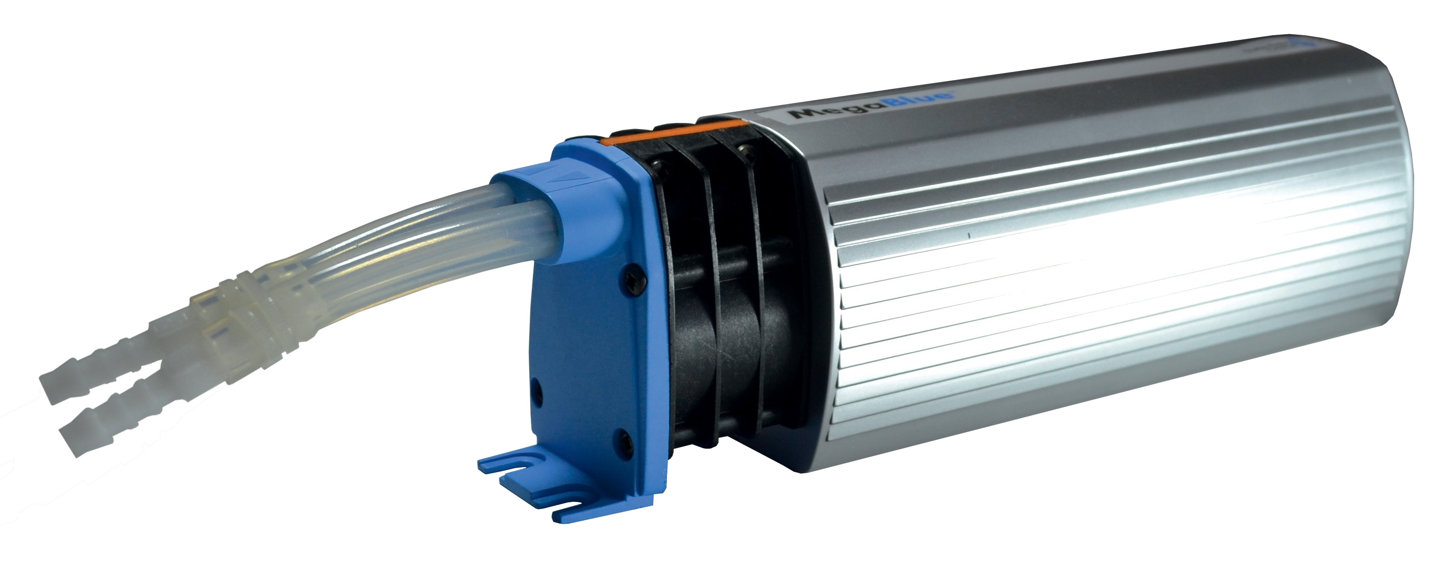
Fuel expansion tanks serve dual purposes: accommodating fuel volume changes with temperature fluctuations and maintaining consistent fuel pressure to the nozzle. The CBM Expansion tank inflator battery 2000 mAH and CBM Megablue reservoir alarm + shut-off X87-813 are critical components for maintaining system stability and providing safety redundancy.
When fuel delivery pressure fluctuates or becomes unstable, the expansion tank system should be the first diagnostic focus. Maintenance teams should follow these assessment procedures:
1. Visual inspection: Examine the expansion tank for external damage, corrosion, or leakage. Check the air-side inflation valve (typically located at the tank top) for corrosion or damage. Corroded valves prevent proper gas exchange, causing system pressure instability.
2. Pressure baseline establishment: Using a calibrated pressure gauge, measure the air-side pressure of the expansion tank with the fuel system depressurized. This baseline pressure (typically 0.5-1.5 bar depending on system design) must be maintained for proper tank functionality. If pressure reads zero or negative, the tank's rubber diaphragm has likely failed.
3. Pressure cycle testing: Operate the burner through a complete heating cycle while monitoring fuel supply pressure continuously. In a functioning system, pressure should remain stable (variation less than ±0.2 bar). Significant pressure fluctuations indicate expansion tank failure, faulty pressure relief valves, or air leaks in the fuel distribution circuit.
4. Diaphragm integrity verification: If tank pressure baseline is absent, the internal diaphragm separating air and fuel sides has failed, allowing fuel to enter the air chamber. This condition requires tank replacement. The CBM Expansion tank inflator battery 2000 mAH provides convenient pressure adjustment; however, if baseline pressure cannot be maintained after reinflation, diaphragm failure is confirmed.
Tank Monitoring and Safety Systems
The CBM Megablue reservoir alarm + shut-off X87-813 provides dual functionality: monitoring fuel level and initiating system shutdown if fuel supply becomes critically low. This system protects against air ingestion and pump cavitation that can damage fuel supply equipment.
Diagnostic procedures for tank monitoring systems:
- Fuel level sensor testing: Manually raise and lower fuel levels while observing sensor output signal. The sensor should transition smoothly from minimum to maximum readings without dead zones or irregular jumps.
- Alarm function verification: With fuel level below the critical threshold, confirm the alarm circuit activates. Listen for audible alarm signals and verify control panel alarm indication illuminates.
- Shut-off valve response: After alarm activation, confirm the fuel supply shut-off valve closes completely within 5-10 seconds, preventing air ingestion into the fuel pump.
If the monitoring system fails to respond appropriately, fuel supply starvation can damage the entire fuel delivery chain including expensive pump assemblies. Test these systems during scheduled maintenance intervals rather than waiting for failure.
Burner Integration and Cross-System Diagnostics
Integrating Fuel Delivery with Burner Performance
The FBR BURNER GAS X5/MF TL EL VC LPG represents modern modulating burner technology where fuel delivery precision directly influences burner performance and flame stability. These burners equipped with optional modulation kits require consistent fuel pressure and atomization to maintain PID (proportional-integral-derivative) control authority.
When burner operation appears unstable but ignition and flame detection systems function normally, the fuel delivery system is frequently the source. Maintenance teams should implement this diagnostic sequence:
1. Nozzle-to-burner pressure balance: Measure fuel pressure immediately upstream of the nozzle and compare against the burner's design specification (marked on the burner nameplate or control documentation). Most industrial burners require 1.0-1.5 MPa at the nozzle. If actual pressure deviates more than ±0.1 MPa from specification, the burner's atomization characteristics change, affecting flame geometry and stability.
2. Air-fuel ratio verification: With the burner operating at rated capacity, observe the flame color and intensity. A properly balanced flame appears relatively uniform yellow-orange with minimal blue zones. Flames that are predominantly blue indicate excess air (fuel starvation), while yellow-orange flames with carbon smoke indicate excess fuel. These conditions often trace to nozzle atomization issues combined with air supply imbalances.
3. Modulation lag measurement: For burners equipped with modulation control, reduce the firing rate command and observe the response delay. The burner should respond smoothly within 2-3 seconds. Sluggish response or oscillation around the commanded firing rate suggests fuel pressure fluctuations or expansion tank dysfunction preventing precise burner control.
4. Cross-system pressure mapping: While the burner operates, simultaneously measure fuel pressure at three points: the supply pump outlet, the expansion tank gauge port, and the nozzle inlet. Plot these pressures over time. In a healthy system, all three measurements should track together with minimal divergence. Divergence between any two points indicates a distribution circuit issue (plugged lines, faulty check valves, or regulator drift).
Systematic Troubleshooting Workflow
When facing unexplained burner performance degradation, maintenance teams should follow this systematic approach:
1. Establish baseline measurements: Record fuel pressure, nozzle flow rate, expansion tank air-side pressure, and burner firing rate before any corrective actions.
2. Isolate variables individually: Test each component (nozzle spray pattern, tank pressure, burner response) in isolation before concluding system-wide failure.
3. Document findings: Maintain detailed records of pressure readings, flow measurements, and response times. This documentation becomes invaluable for identifying degradation patterns and predicting future failures.
4. Implement preventive replacements: Based on historical data and manufacturer recommendations, plan scheduled nozzle replacement every 2-3 years and expansion tank diaphragm replacement every 5-7 years, preventing catastrophic failures during critical operating periods.
With over 35 years of experience supporting global industrial operations, 3G Electric emphasizes that most fuel delivery failures are preventable through systematic monitoring and planned maintenance. The components referenced in this guide—precision nozzles, pressure regulation equipment, and tank monitoring systems—represent proven technology that, when properly maintained, delivers exceptional reliability and combustion efficiency for industrial applications worldwide.