Flame Detection and Monitoring Systems: A Technical Guide to Controls & Safety for Global Industrial Burners
Flame detection and monitoring represents a critical safety layer in modern industrial burner control architecture. Whether managing atmospheric gas burners, fuel oil systems, or biomass applications, the ability to reliably detect and verify flame presence determines both operational safety and system reliability. This technical guide addresses the sensor technologies, integration methodologies, and commissioning procedures that maintenance teams and service engineers must understand to design, install, and maintain effective flame monitoring systems across global industrial applications. We'll examine infrared detection, photo-resistive sensing, and control relay integration—the three foundational elements that work together to protect personnel and equipment.
Core Technology: How Flame Detection Systems Function
Flame detection operates on the fundamental principle of converting visible or infrared light energy from an active flame into an electrical signal that control systems can recognize and act upon. Industrial burner controls require this signal to perform two critical functions: confirm that ignition was successful during the startup sequence, and continuously monitor flame stability during operation to enable rapid shutdown if flame loss occurs.
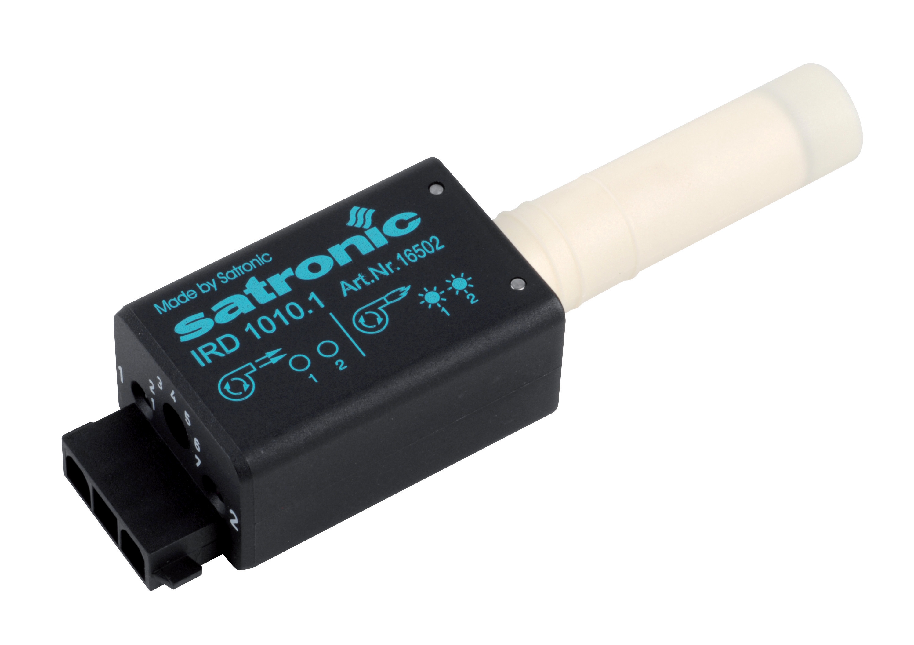
Modern flame detection systems employ three primary sensing technologies, each suited to specific fuel types and operational environments. Infrared (IR) flame detectors respond to radiation in the 800–1100 nanometer wavelength range, making them particularly effective for monitoring fuel oil and biomass flames that generate strong infrared signatures. Photo-resistive cells operate on a different principle, detecting visible light through changes in electrical resistance—a cost-effective approach suitable for applications where flame characteristics remain stable. Phototransistor-based sensors represent the third category, offering improved sensitivity and faster response times compared to older photo-resistive technology, with the added benefit of RoHS 2011/65/EU compliance for regulated markets.
The choice between these technologies depends on multiple factors: fuel type, flame color and stability, ambient light conditions, and the specific safety and operational requirements of the burner system. Infrared sensors excel in outdoor or high-ambient-light environments because daylight filters (typically 950 nm maximum) eliminate false signals from sunlight. Photo-resistive cells, conversely, perform best in controlled indoor environments where ambient light remains relatively constant. All three technologies integrate with safety control relays that interpret the sensor signal and generate the command logic necessary to maintain or terminate burner operation.
Technical Specifications and Product Integration
Understanding the technical specifications of flame detection components is essential for proper system design and troubleshooting. The CBM IRD 1010 blue cell represents a modern infrared flame detector specifically engineered for fuel flame monitoring. This device operates across a spectral range of 800–1100 nm, with maximum sensitivity at 950 nm when a daylight filter is engaged—a critical feature for systems exposed to direct sunlight or strong ambient lighting. The device accepts a supply voltage of 220/240 V with a tolerance of −15% to +10%, ensuring compatibility with standard industrial electrical supplies. Its frequency response range of 15–250 Hz (−12 dB) enables detection of flame flicker patterns typical of fuel burners while rejecting electrical noise. The IP 41 protection rating confirms suitability for typical industrial environments where dust and light moisture exposure occurs. Mounting position flexibility (any orientation) simplifies installation in confined burner chambers.
The CBM Cell 8207 photo-resistive flame sensor offers an alternative approach for applications where infrared detection is less suitable. As a photo-resistive device, it converts visible light intensity into electrical resistance changes that control relays monitor and interpret. The maximum operating temperature specification of 100°C defines the thermal ceiling for continuous operation—a critical parameter when mounting sensors in proximity to hot burner components. This sensor integrates with control equipment featuring amplification circuits that translate resistance changes into binary flame/no-flame signals.
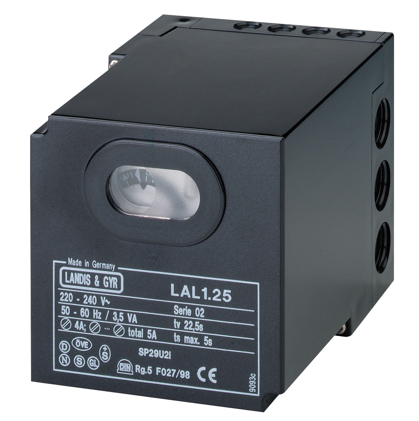
Safety control relays serve as the decision-making layer between sensor input and burner command output. The CBM Relay LAL 2.14 exemplifies modern burner safety control architecture for intermittent service applications including universal burners and hot air generators. This relay accepts input from multiple flame detection technologies: the QRB1 infrared detector, QRC1 blue flame sensors, or RAR photo-electric cells. By supporting three distinct sensor types, the LAL 2.14 provides flexibility for maintenance teams managing diverse burner fleets across different fuel types and operational environments. The relay performs non-volatile lock-out functions—a safety feature that prevents automatic restart following flame loss or ignition failure, requiring manual intervention to reset the system and diagnose the underlying fault.
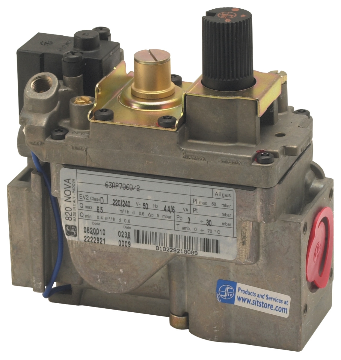
For automatic gas burner applications with more complex control requirements, the CBM Relay CM391.2 30.5 1.2 delivers electronic control logic designed specifically for atmospheric and fan-assisted burners in intermittent operation mode. This EUROBOX series relay incorporates non-volatile lock-out protection and operates reliably across the full range of gas fuel types and combustion conditions typical in industrial and commercial applications.
Installation and Commissioning Procedure for Flame Detection Systems
Step 1: Pre-Installation Assessment
Before sensor installation, conduct a detailed survey of the burner chamber environment. Document ambient light levels, temperature profiles, fuel type, and expected flame color. For outdoor or high-ambient-light applications, infrared detection becomes mandatory. For indoor fuel oil burners with stable operating conditions, photo-resistive or phototransistor sensors may provide cost-effective alternatives. Verify that the control relay you have selected accepts the flame detection technology you intend to deploy.
Step 2: Sensor Positioning and Optical Path
Position the flame sensor to achieve a clear, unobstructed view of the active flame. The sensor must detect the flame directly without obstruction by combustion chamber walls, burner nozzles, or flame stabilization equipment. For infrared sensors, avoid positioning where heat radiation from hot surfaces (but not flames) dominates the optical field—this creates false flame signals. Mount the sensor perpendicular to the expected flame front when possible to maximize signal strength. Secure the sensor with appropriate mechanical supports and verify that vibration or thermal expansion cannot shift the optical alignment during operation.
Step 3: Electrical Connection and Safety Verification
Wire the sensor output to the designated flame detection input on your safety control relay, following the relay's wiring diagram precisely. Verify that the sensor supply voltage matches the relay specification (typically 220/240 V AC for industrial systems). Conduct an insulation resistance test on all sensor wiring to detect faults before energization. Document the sensor model and serial number in your maintenance records.
Step 4: Commissioning and Flame Detection Testing
Energize the system and observe the control relay's flame detection indicator light or digital display. Initiate burner ignition and confirm that the flame detection signal activates within the manufacturer's specified response time (typically 1–3 seconds for modern systems). Perform a flame loss test by interrupting the fuel supply and verifying that the safety relay shuts down the burner and activates the lock-out function. Document the response time and reset procedure in your operational manual.
Selection Criteria and Best Practices for Global Applications
Match Sensor Type to Fuel and Environment: Infrared detection excels for fuel oil, biomass, and any outdoor burner application. Photo-resistive and phototransistor sensors suit stable indoor environments with consistent ambient lighting. For systems operating in variable lighting conditions or high-temperature environments, prioritize infrared technology with daylight filtering capability.
Specify Control Relays with Multi-Sensor Flexibility: Select safety relays like the LAL 2.14 that accept multiple flame detection technologies. This design philosophy simplifies parts inventory management and enables field technicians to retrofit sensors when environmental conditions change or maintenance requirements evolve.
Implement Preventive Sensor Maintenance: Infrared windows and photo-resistive cell surfaces accumulate combustion residue, dust, and corrosion products that degrade optical clarity and reduce detection sensitivity. Establish a quarterly cleaning schedule using soft, non-abrasive materials. For systems operating in high-contamination environments, reduce inspection intervals to monthly. Document all cleaning and maintenance actions in your burner service log to establish performance baselines and support troubleshooting.
Design for Thermal Management: Ensure adequate ventilation around flame sensors to prevent excessive temperature rise. Photo-resistive cells must remain below 100°C during continuous operation; thermal design failures are a common cause of false no-flame conditions during high-load burner operation. When installing multiple sensors or sensors in confined spaces, use thermal modeling to predict steady-state temperatures and adjust mounting positions accordingly.
Coordinate Sensor Selection with Pilot Light Strategy: In systems using pilot lights for ignition, coordinate flame detection sensor placement to ensure the pilot flame and main flame are both monitored according to your safety control logic. The CBM Pilot light 1 flame 0140026 delivers silent, highly corrosion-resistant operation with rapid thermocouple substitution capability—key attributes when integrating pilot ignition with main-flame detection in a unified safety architecture.
Troubleshooting Common Flame Detection Failures
Nuisance lock-outs (false flame-loss events) commonly result from optical window contamination, sensor misalignment, or inadequate daylight filtering in high-ambient-light environments. Corrective measures include cleaning optical surfaces, verifying sensor mounting security, and confirming proper installation of daylight filters on infrared sensors. Failure to detect actual flame typically indicates optical path obstruction, incorrect sensor-to-relay wiring, or a sensor operating beyond its maximum temperature specification. Systematic visual inspection of the optical path, continuity testing of electrical connections, and temperature measurement at the sensor body all contribute to rapid fault isolation.
Conclusion and Next Steps
Effective flame detection and monitoring systems represent the intersection of sensor technology, control logic, and rigorous commissioning discipline. By understanding the operating principles of infrared, photo-resistive, and phototransistor-based sensors, and by selecting safety control relays that support multiple detection technologies, maintenance teams can design flexible, reliable burner control architectures suited to diverse global industrial applications. Proper installation positioning, thermal management, and preventive sensor maintenance ensure long-term system reliability and operator safety.
3G Electric has partnered with leading controls and safety manufacturers to supply the flame detection sensors and safety control relays your team needs. Whether you're specifying infrared detectors for outdoor fuel oil burners, photo-resistive cells for stable indoor applications, or integrated safety relays supporting multiple sensor types, our technical team can help match products to your operational requirements and provide commissioning support across global markets. Browse our complete controls and safety product range, or explore our specialized flame detection sensors and monitoring components. For detailed technical consultation or support with system integration and commissioning procedures, contact the 3G Electric team to discuss your specific application requirements.