Understanding Controls & Safety Through Electrical Interlocking Architecture
Controls & Safety in modern industrial HVAC systems extends far beyond simple on/off switching. At the heart of every reliable burner installation lies a coordinated sequence of electrical interlocks that prevent unsafe operating conditions before they develop. For HVAC contractors operating in Singapore's hot, humid climate—where equipment stress is amplified by salt spray corrosion and temperature extremes—understanding electrical interlock architecture is essential to system longevity and occupant safety.
Electrical interlocking achieves two critical objectives: it prevents concurrent conditions that would damage equipment (like ignition without airflow), and it creates predictable shutdown sequences when any safety parameter fails. Rather than relying on a single sensor or relay, modern Controls & Safety architecture uses distributed logic where multiple components must confirm safe conditions before the next sequence step executes.
3G Electric has supplied HVAC contractors across Southeast Asia for over 35 years, and we've observed that interlock failures typically stem not from component defects, but from poorly understood sequence timing and inadequate field troubleshooting protocols. This article addresses that gap.
Core Interlock Sequences: Pre-Purge, Ignition, and Flame Confirmation
Pre-Purge Interlock Logic
Before any ignition can occur, burner safety standards (including Singapore's adoption of EN 746-2) mandate a pre-purge period where air flows through the combustion chamber to clear any accumulated fuel vapors. This sequence prevents explosive conditions during startup.
The pre-purge interlock works like this:
1. Demand signal received — Thermostat or building management system requests heat
2. Lockout timer reset — Any previous fault codes are cleared (if manual reset is configured)
3. Fan motor energized — Air handling unit begins rotation; airflow switch waits for confirmed flow
4. Airflow confirmation delay — Typically 2–5 seconds; the airflow switch must close and remain closed
5. Pre-purge timer starts — Relay begins counting, commonly 30–60 seconds depending on appliance size
6. Pre-purge timer expires — Only then can the ignition relay be energized
In Singapore's humidity, moisture accumulation in ductwork can slow airflow confirmation. Contractors should verify that airflow switches are mounted in a location free from condensation drips, and that the switch threshold is not set too sensitively (which causes nuisance trips on humid mornings).
The Kromschroder BCU 570WC1F1U0K1-E relay integrates this sequence logic into a single control unit, accepting airflow closure as an input and enforcing the pre-purge dwell before releasing the ignition signal. This reduces external wiring complexity and single points of failure.
Ignition Interlock and Flame Confirmation Window
Once pre-purge completes, the ignition relay energizes the spark electrode and the pilot gas solenoid simultaneously. The flame detection circuit now enters a critical "confirmation window"—typically 4–8 seconds—during which the flame sensor must report a stable flame signal.
If flame is not detected within this window:
- The ignition relay de-energizes
- A "trial for ignition" counter increments
- After 2–3 failed ignition trials, the burner enters lockout
- The lockout relay prevents any further ignition attempts until manually reset
This interlock prevents dangerous accumulation of unburned fuel in the combustion chamber. A failed ignition that goes undetected could lead to a delayed explosion when fuel eventually ignites.
The Pactrol Housing P 16 DI CE flame control module implements this logic with precise timing: it monitors the flame detection signal during the confirmation window and coordinates the ignition output voltage (12 kV, 10MJ energy) to ensure reliable spark.
Sustained Flame Interlock During Operation
Once flame is confirmed, the burner enters "on" mode. But the flame interlock does not stop monitoring. Throughout operation, the flame sensor continuously reports flame presence. If the flame signal drops below threshold for more than a brief moment (typically 0.5–2 seconds, depending on configuration), the burner must shut down safely.
In Singapore's industrial environment—especially in facilities near the coast—salt spray and moisture can degrade flame sensor windows over time, causing intermittent signal loss. Contractors should schedule quarterly flame sensor inspection, including optical cleaning and continuity testing of sensor leads.
Pressure Interlock Sequences: Managing Gas and Air Dynamics
Pressure interlocks form the second pillar of Controls & Safety architecture. Unlike flame detection, which responds to combustion, pressure interlocks prevent operating conditions where pressure relationships are unsafe.
Gas Supply Pressure Interlock
Most industrial gas burners require minimum inlet pressure to atomize fuel effectively and maintain stable combustion. A low-gas-pressure interlock (typically set 3–5 psi below normal operating pressure) prevents the burner from remaining on if gas supply fails or drops unexpectedly.
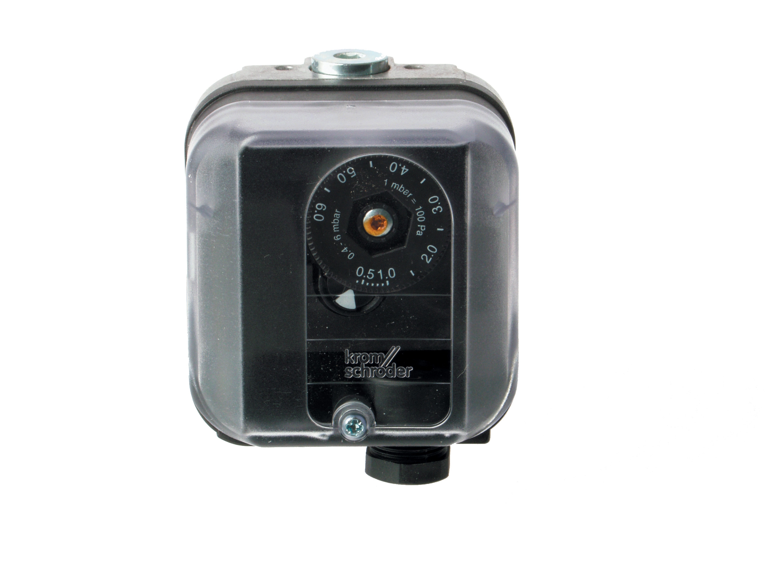
The Kromschroder DG 50U/6 pressure switch is rated SIL 3 and Performance Level e, meaning it is suitable for safety-critical applications where dangerous failure modes must be quantified and managed. In Singapore's industrial context, where gas supply can be interrupted during peak demand periods, this redundancy prevents uncontrolled fuel accumulation.
Pressure switch configuration requires careful field adjustment:
- Setpoint: Usually 10% below minimum expected operating pressure
- Deadband: The pressure rise required to re-close the switch after activation (typically 1–2 psi)
- Connection location: Pressure must be tapped upstream of all modulating valves to sense true supply pressure
If a pressure switch is installed downstream of a modulating gas block, it will not detect upstream supply failure—a configuration error common in retrofit projects.
Combustion Air Pressure Interlock
For burners with forced-draft fans, combustion air pressure interlocks ensure that the air supply meets minimum flow requirements. Unlike simple airflow switches (which only confirm rotation), pressure interlocks measure the actual dynamic pressure produced by the fan.
This distinction is important: a fan could rotate but produce inadequate pressure if the wheel is fouled with dust, or if ductwork is partially blocked. In Singapore's tropical environment, where dust storms and salt spray can coat equipment rapidly, this scenario is plausible.
Air pressure interlocks are usually mounted on the air inlet manifold and preset to the minimum pressure the fan should produce at full speed. If pressure drops below this threshold (indicating fan degradation or blockage), the interlock de-energizes and prevents fuel injection.
Load Modulation and Proportional Valve Interlocking
As building thermal loads vary, burners must modulate fuel input to maintain setpoint temperature while minimizing short-cycling and energy waste. Proportional modulation introduces additional interlock complexity because the gas block (or proportional valve) must coordinate with multiple sensors.
Modulating Gas Block Architecture
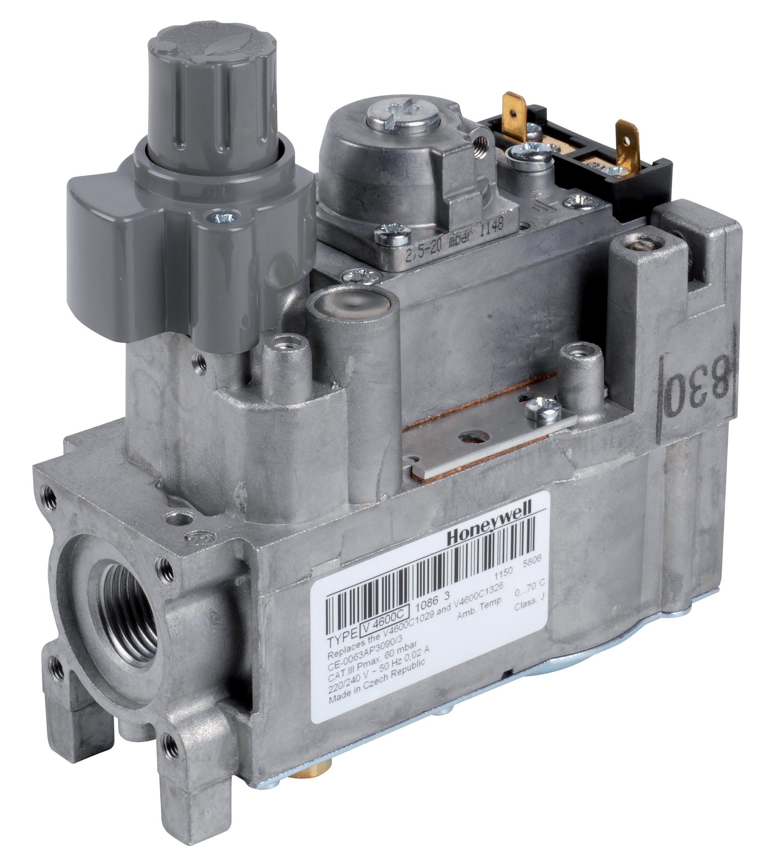
The Honeywell VK 4105 C 1041 U modulating pressure regulator accepts a control signal (typically 0–10 VDC from the building control system) and adjusts outlet gas pressure proportionally. This allows smooth burner modulation without discrete on/off cycling.
However, modulating valves introduce an interlock requirement: the valve position must be verifiable. Most modulating gas blocks include a feedback signal (0–10 VDC proportional to valve position) that the control relay monitors. If the valve position feedback does not follow the control command—indicating a stuck valve or actuator failure—the interlock must signal a fault condition.
This requires a safety control relay like the Siemens LFL 1.622, which accepts the valve feedback signal, compares it against the command signal, and verifies that discrepancy stays within an acceptable band. If the valve appears stuck, the relay initiates safe shutdown.
In Singapore's climate, where salt corrosion can affect solenoid valve plungers, this feedback monitoring is not a luxury—it is essential to catch valve degradation before it causes unsafe conditions.
Setpoint Ramp-Down Interlocking
When a thermostat call-for-heat ends, proportional burners must ramp down fuel input gradually rather than shutting off abruptly. This ramp-down prevents pressure spikes in the combustion chamber and allows the control system to confirm that flame will not drop to zero prematurely.
The ramp-down interlock typically:
1. Receives a "heat off" signal from the thermostat
2. Commands the modulating valve toward minimum position over 10–30 seconds
3. Monitors the flame signal throughout the ramp
4. If flame drops prematurely, halts the ramp and restores fuel input (indicating a burner tuning problem)
5. If flame remains stable through the ramp, allows valve to reach minimum at the end of the timer
6. Monitors for a few more seconds to confirm stable low-fire operation
7. Only then de-energizes the ignition and fuel solenoids
This coordinated sequence prevents dangerous flame-out events during load reduction.
Field Installation and Troubleshooting Guidelines for Singapore HVAC Contractors
Wiring Routing and Environmental Hardening
In Singapore's saline, humid environment, electrical interlock wiring requires aggressive corrosion protection:
- Use marine-grade stainless steel conduit in any outdoor or semi-outdoor section
- Seal all junction boxes with silicone conformal coating after final commissioning
- Install desiccant breathers in any control enclosure exposed to daily humidity swings
- Verify continuity on all safety circuits monthly—especially flame sensor and pressure switch leads, which are prone to corrosion-induced open circuits
Commissioning Sequence Verification
Before handover, contractors must verify the entire interlock sequence with a systematic test plan:
1. Pre-purge timing: Disconnect the airflow switch; verify that the ignition relay will not energize. Reconnect the airflow switch; confirm that pre-purge timer counts and ignition energizes after the timer expires.
2. Ignition trial limit: Block the pilot flame (cover the spark electrode); count the number of ignition attempts before lockout occurs. Verify it matches the relay setting (typically 3).
3. Flame interlock during operation: Start the burner normally. While flame is stable, briefly interrupt the flame sensor signal; verify the burner shuts down within 2 seconds.
4. Gas pressure interlock: With the burner running, manually reduce gas supply pressure below the pressure switch setpoint. The burner should de-energize immediately.
5. Proportional valve feedback (if equipped): With the valve energized, confirm that the feedback signal follows the command signal. Simulate a stuck valve by manually restricting valve movement; verify the control relay signals a fault.
Document all test results and retain them for the facility's maintenance file. Singapore's growing emphasis on building safety compliance (aligned with international standards) makes commissioning records valuable evidence of proper installation.
Common Interlock Faults and Root Cause Analysis
Symptom: Burner locks out after 1–2 ignition attempts.
- Check 1: Verify airflow switch is closed and latched before ignition is allowed.
- Check 2: Inspect flame sensor window for dust or salt spray accumulation; clean with soft cloth and methanol.
- Check 3: Verify pilot gas solenoid is energizing (listen for audible click; measure 24 VDC across solenoid coil).
- Check 4: Confirm pilot gas pressure is adequate (usually 3–5 psi); if low, check the gas supply shutoff valve and meter regulator.
- Check 1: Verify that flame interlock is not over-sensitive. Most flame sensors include a potentiometer adjustment; if set too high, noise from electrical interference causes nuisance flame loss signals.
- Check 2: Inspect flame sensor leads for loose connections or corrosion.
- Check 3: If the burner is modulating, verify that the proportional valve is not oscillating (stuttering). If it is, the feedback signal may be noisy; shield the feedback wiring separately from power wiring.
- Check 1: Verify the pressure switch is not downstream of a shutoff valve that is partially closed.
- Check 2: Confirm the pressure switch connection is not clogged; blow out the pressure tap with compressed air (gently—do not exceed 30 psi).
- Check 3: If the pressure switch is part of a 3G Electric packaged solution, verify the setpoint matches the system's operating pressure.
Maintenance and Long-Term Reliability in Tropical Climates
Electrical interlock systems age predictably in Singapore's climate. Establish a preventive maintenance schedule:
Monthly: Visual inspection of control enclosure for moisture ingress or salt accumulation.
Quarterly: Clean flame sensor windows; test flame interlock by briefly shading the sensor.
Semi-annually: Measure solenoid coil resistance (typically 20–40 ohms for 24 VDC coils); open circuits or significantly lower resistance indicate imminent failure.
Annually: Recalibrate pressure switches by comparing their response against a calibrated test gauge.
By maintaining interlock systems proactively, contractors protect their customers' equipment and avoid emergency service calls during peak cooling seasons—when downtime costs are highest.
Conclusion
Controls & Safety through electrical interlocking is not a static compliance exercise; it is a dynamic coordination of sensors, relays, and solenoids that must respond reliably to hundreds of operating cycles daily. Singapore's challenging climate—with salt spray, humidity, and temperature extremes—demands components and practices that exceed minimum standards.
3G Electric's 35+ years serving HVAC contractors across Southeast Asia has taught us that system reliability comes from understanding the "why" behind interlock sequences, not just the "what." When contractors grasp why pre-purge matters, why flame confirmation windows exist, and how pressure interlocks protect equipment, they can install systems that perform consistently and troubleshoot failures logically.
Partner with 3G Electric for Controls & Safety components and technical guidance that keep Singapore's industrial HVAC systems running safely and efficiently.