Flame Detection vs. Burner Control Relays: A Technical Comparison for Industrial Combustion Systems
Industrial burner systems depend on two critical safety layers: flame detection sensors that identify combustion presence, and control relays that manage the entire ignition and operational sequence. While these technologies often work together, they serve distinctly different functions in combustion systems globally. For maintenance teams and service engineers, understanding the architectural and operational differences between flame detection sensors and burner control relays is essential for system troubleshooting, equipment selection, and ensuring reliable combustion safety. This comparison examines how these technologies differ in design, application, performance specifications, and integration requirements—helping you make informed decisions about which systems suit your industrial facility's specific operational needs.
Understanding the Core Functional Difference
Flame detection sensors and burner control relays operate at fundamentally different levels of the combustion system hierarchy. A flame detection sensor is a passive monitoring device that continuously observes the burner flame and generates an electrical signal in response to light or radiation emitted during combustion. This signal indicates only one thing: whether flame is present or absent. In contrast, a burner control relay is an active command system that orchestrates the entire sequence of burner operation—from ignition activation through fuel valve control, air damper adjustment, and safety interlocks. The relay makes decisions based on multiple inputs, including the flame detection signal, temperature readings, pressure measurements, and timing parameters.
Think of it this way: the flame detection sensor is a watchdog that reports what it observes, while the control relay is the decision-maker that acts on that observation. A properly functioning flame detection sensor may report flame present, but a faulty control relay might fail to shut down the burner when it should, or conversely, might cut fuel supply even when the sensor confirms flame is burning. This distinction matters because system failures can occur at either level—a dead flame detector will blind the system to actual flame loss, while a failed control relay will ignore the flame detector's warning signals entirely.
The integration point between these two technologies is critical: the flame detector output becomes one input among many that the control relay monitors. Different burner architectures use different detection methods (infrared, ultraviolet, phototransistor), and different control relay designs are optimized for specific fuel types, operating modes (intermittent vs. continuous), and burner styles (atmospheric vs. forced-draught). Understanding this relationship helps maintenance teams diagnose problems more accurately and select compatible replacement components.
Flame Detection Technologies: Specifications and Application Context
Industrial flame detection has evolved across three primary sensor technologies, each with distinct spectral sensitivity and environmental tolerance. The CBM IRD 1010 infrared flame detector represents modern spectral-selective detection, operating in the 800–1100 nm infrared range with maximum sensitivity at 950 nm when equipped with a daylight filter. This narrow spectral window makes infrared detectors highly resistant to ambient light interference and ideal for outdoor installations or facilities with high-intensity lighting. The IRD 1010 accepts mounting in any orientation and maintains protection rating IP 41, making it suitable for harsh industrial environments. Supply voltage tolerance of ±15% to +10% from nominal 220–240 V ensures reliable operation even in facilities with variable electrical supply.
In contrast, phototransistor-based sensors like the CBM Cell FC11 phototransistor flame sensor (now superseded by the FT11-V model) offer broadband visible-light detection optimized for oil and biomass burners where flame coloration varies significantly. Phototransistor designs are inherently faster-responding than photo-resistive cells and comply with modern RoHS directives, making them suitable for new installations requiring environmental compliance. Photo-resistive cells represent the legacy technology but remain in service across many installed systems; the CBM Cell 8207 photo-resistive sensor operates with maximum temperature tolerance of 100°C during normal service and requires amplification equipment for operation with miniature control series.
The choice between these detection technologies depends on fuel type, flame color predictability, ambient lighting conditions, and the control relay architecture. Natural gas flames burn blue and relatively consistently, making them suitable for ultraviolet or narrowband infrared detection. Oil burners produce yellow-orange flames susceptible to ambient light interference, making infrared or phototransistor detection more reliable. Maintenance teams must match flame detector selection to both the installed control relay specifications and the facility's environmental conditions. A facility with high-intensity metal halide work lights will fail repeatedly with broadband photo-resistive detection but operate reliably with infrared detection. Similarly, replacing an ultraviolet detector with infrared on an oil burner application may work temporarily but will sacrifice sensitivity margin designed into the original system.
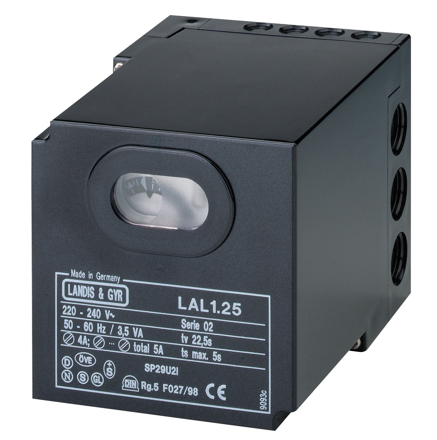
Burner Control Relays: Architecture, Operation, and Fuel-Type Specificity
Burner control relays divide into two functional categories: gas burner controls and oil burner controls, each designed for the distinct combustion characteristics and safety requirements of their respective fuel types. Gas burner control relays like the CBM Relay CM391.2 30.5 1.2 operate in the EUROBOX series architecture specifically for intermittent automatic gas burner control on atmospheric and fan-assisted burners. These relays incorporate non-volatile lock-out functions—a critical safety feature that forces manual restart following a flame-out condition, preventing automatic ignition cycles that could create dangerous fuel accumulation.
The CBM Relay LAL 2.14 represents a different control architecture optimized for oil burners and universal applications including hot air generators and steam boilers. This relay accepts multiple flame monitoring inputs—QRB1 ultraviolet detectors, QRC1 blue flame sensors, or RAR photo-electric cells—allowing flexibility in retrofit scenarios where facility maintenance teams must integrate new control systems with existing flame detection equipment. This modularity reflects a key architectural principle: while gas and oil burners share basic control logic (ignition sequence, flame monitoring, shutoff), the response times, pressure specifications, and fuel valve characteristics differ sufficiently to require separate relay designs.
Control relay performance specifications reveal critical operational constraints. Supply voltage tolerance, frequency response range (measured in Hz), rated electrical loads (expressed in amperes at specific voltages), and mechanical endurance (rated in cycles or operations) all determine system reliability under actual industrial conditions. The CBM Flame relay CF1 exemplifies a compact single-function relay accepting up to 10 ultraviolet detectors on detector lines up to 50 meters long, with rated load capacity of 1 A @ 250 VAC or 1 A @ 30 VDC and mechanical endurance of 15×10⁶ operations. For maintenance teams, understanding these specifications means recognizing that exceeding rated load capacity or extending detector line length beyond specification will degrade system response time and safety margin, potentially leading to undetected flame-loss conditions.
System Integration: How Flame Detection and Control Relays Work Together
A properly integrated combustion system functions as a multi-stage safety architecture where flame detection and control relay functions operate in complementary sequence. During normal startup, the control relay energizes the ignition transformer and opens the fuel valve. Simultaneously, it begins monitoring the flame detector output. If the detector signals flame presence within the prescribed ignition timing window (typically 3–5 seconds for gas burners), the relay energizes the main fuel solenoid valve to transition from ignition to steady-state combustion. The flame detector continues monitoring throughout operation; if the signal is lost for any reason—blockage of the detector lens, fuel supply interruption, or actual flame extinction—the relay detects this change and initiates shutdown, closing the fuel valve and de-energizing the ignition circuit.
The integration point between detector and relay determines system safety margin. A slow-responding detector combined with a relay configured for rapid reaction time creates a mismatch that can cause nuisance shutdowns or, conversely, delayed response to actual flame loss. A fast-responding detector paired with a relay configured with long ignition timing creates the opposite risk: the relay may ignore valid flame signals because it interprets them as noise rather than established combustion. This is why matching detector type and control relay series is essential—manufacturers design these pairs with coordinated response characteristics.
Integration complexity increases when modulating burners enter the picture. The FBR BURNER GAS X5/MF TL EL VC LPG incorporates full PID (proportional-integral-derivative) modulating capability when equipped with an optional modulation kit and temperature probe. This architecture requires a more sophisticated control relay than simple on-off combustion control, as the relay must process continuous proportional feedback from the probe and adjust fuel flow to maintain target temperature within a narrow band. Standard flame detection relays cannot manage this function; modulating burners require specialized modulation-capable control systems that accept analog feedback inputs.
Real-World Application Scenarios
Scenario 1: Industrial Steam Boiler with Oil Burner A manufacturing facility operates a 500-kg/h steam boiler with an oil burner serving facility heating and process steam demands. The original ultraviolet flame detector and control relay have served reliably for 15 years, but the facility experiences periodic nuisance shutdowns during afternoon shifts when bright sunlight enters the boiler room through high windows. The maintenance team suspects UV light interference, but before replacing the detector, they consult the control relay specification and discover it's rated for 50–100 Hz operation. Upgrading to the infrared-based IRD 1010 detector operating at the same frequency eliminates the shutdowns by rejecting visible and near-infrared ambient light, while maintaining identical electrical integration with the existing relay.
Scenario 2: Gas Burner Control Upgrade in HVAC Application A regional HVAC contractor must retrofit a warm-air generator with a modern safety-certified control system. The facility has an existing forced-draught gas burner with proven performance but aging control electronics. Rather than replacing the entire burner, the contractor selects the CBM CM391.2 relay specifically designed for forced-draught gas burner control with non-volatile lock-out, paired with a CBM CF1 flame relay accepting the facility's existing ultraviolet detector assembly. This approach preserves the burner investment while upgrading to current safety standards and providing full backward compatibility with existing detection infrastructure.
Scenario 3: Modulating Natural Gas Burner Integration A food processing facility requires precise temperature control for an industrial oven heated by a natural gas burner. Standard on-off combustion control creates temperature swings of ±15°C, affecting product quality. The facility upgrades to the FBR BURNER GAS X5/MF with modulation kit and probe, but discovers that their existing control relay cannot process the analog modulation signal. They upgrade to a modulation-capable control system that accepts the temperature probe input, monitors the flame detector output, and adjusts fuel supply via proportional valve control to maintain temperature within ±2°C—dramatically improving product consistency.
Technical Comparison: Key Specifications Across Detection and Control Technologies
| Technology | Type/Model | Primary Application | Key Specification | Environmental Tolerance |
|---|---|---|---|---|
| Infrared Detector | CBM IRD 1010 | Fuel flame monitoring | 800–1100 nm spectral range; any mounting position | IP 41; high ambient light rejection |
| Phototransistor | CBM Cell FC11/FT11 | Oil or biomass burners | Fast response; broadband visible detection | RoHS compliant; modern environmental compliance |
| Photo-Resistive Cell | CBM Cell 8207 | Legacy burner systems | Max operating temp 100°C; requires amplification | Requires miniature series support equipment |
| Gas Burner Relay | CBM CM391.2 | Intermittent gas burner control | Forced-draught capability; non-volatile lock-out | Atmospheric and fan-assisted burners |
| Oil Burner Relay | CBM LAL 2.14 | Oil burner safety control | Multi-detector compatibility (QRB1, QRC1, RAR) | Universal burner types; retrofit flexibility |
| Compact Flame Relay | CBM CF1 | UV detector integration | 15×10⁶ mechanical cycles; 1 A @ 250 VAC rated load | Supports up to 10 detectors on 50 m lines |
| Modulating Burner | FBR GAS X5/MF | PID modulation with probe feedback | Range 69.8–349 kW; IP 40 protection | Requires modulation-capable control relay |
Selecting the Right Combination for Your Facility
Choosing between flame detection sensors and control relay systems is not an either-or decision—industrial combustion requires both working together. Your selection criteria should focus on matching compatible technologies to your specific facility profile. First, identify your fuel type: gas burners and oil burners have fundamentally different safety requirements, and mixing architectures (gas relay with oil detector, for example) will fail. Second, assess your environmental conditions: facilities with high ambient lighting require infrared detection; underground or shielded locations can use ultraviolet. Third, determine your operating mode: intermittent burners (startup each cycle) require different relay designs than continuous-duty applications. Fourth, evaluate your control precision needs: standard on-off operation uses basic flame relays, while precise temperature or pressure control requires modulating burners integrated with proportional control systems.
For retrofit or replacement scenarios, document your current system specifications before ordering components. A maintenance team cannot simply substitute a newer flame detector model without verifying that the existing control relay accepts that detector type and spectral range. Similarly, upgrading to a modern control relay without confirming compatibility with installed flame detection equipment will result in integration failures. When in doubt, consult the technical documentation for both components or engage with your industrial equipment supplier to validate compatibility before ordering.
Partnering with Industrial Equipment Specialists
Navigating the technical landscape of burners & combustion equipment requires expertise that extends beyond product datasheets. Industrial equipment distributors serving global markets maintain technical specialists who understand the integration requirements between flame detection and control relay systems across diverse fuel types, operating modes, and environmental conditions. When selecting replacement components or upgrading burner systems, consulting with experienced professionals helps avoid costly installation failures and ensures your combustion systems meet current safety standards while optimizing operational reliability.
At 3G Electric, we have served industrial facilities since 1990 with combustion system expertise covering natural gas, LPG, and oil burner technologies across applications from HVAC to process heating. Our technical team understands the architectural differences between flame detection sensors and control relay systems and can help you navigate compatibility requirements, performance specifications, and facility-specific integration challenges. Whether you are troubleshooting an existing combustion system, planning an equipment upgrade, or implementing a facility-wide modernization program, we provide access to proven industrial-grade components paired with technical guidance that ensures reliable, safe operation.
Contact 3G Electric today to discuss your burner and combustion control requirements. Our specialists are ready to help you evaluate flame detection and control relay options specific to your facility's fuel type, operating mode, and environmental conditions—ensuring you select compatible, code-compliant systems that deliver years of reliable service.