Electrical Safety Testing and Measurement Equipment Troubleshooting: A Comprehensive Guide for Maintenance Teams
Electrical safety testing and measurement equipment forms the backbone of preventive maintenance in industrial facilities worldwide. When these instruments fail or produce unreliable readings, operations grind to a halt and safety risks escalate dramatically. Unlike pressure gauges or temperature sensors that provide process data, electrical testing equipment—non-contact voltage detectors, digital multimeters, and thermocouples—directly validate the safety of electrical systems. This guide addresses the unique troubleshooting challenges facing maintenance teams globally who depend on these instruments for daily operations. We'll explore diagnostic protocols, common failure modes, and practical solutions to restore measurement accuracy and operational confidence.
Understanding Electrical Measurement Equipment Failure Modes
Electrical testing instruments fail through distinct mechanisms that differ fundamentally from passive pressure or temperature gauges. Unlike mechanical pressure gauges that rely on Bourdon tube physics, electrical testers contain active electronic components—batteries, circuits, sensors, and displays—that degrade predictably over time and usage cycles.
The primary failure categories include battery depletion, probe/contact degradation, internal circuit failures, and calibration drift. Battery-powered devices like non-contact voltage detectors and automatic multimeters experience battery-related failures as the leading cause of field errors—not because the circuitry fails, but because aging batteries deliver insufficient voltage to power sensitive detection circuits. A multimeter operating at 50% battery capacity may show false readings or trigger low-battery warnings on the display before complete failure.
Probe and contact degradation occurs when the metallic contact points corrode, oxidize, or physically wear. In harsh industrial environments—shipyards, chemical processing plants, food manufacturing facilities—atmospheric corrosion accelerates this degradation. Temperature-measurement probes like Type K thermocouples suffer additional stress from thermal cycling; repeated exposure to high-temperature gradients can cause junction degradation and open-circuit failures.
Internal circuit failures manifest as intermittent readings, frozen displays, or complete unresponsiveness. These often result from moisture ingress, electrical surges from nearby equipment, or manufacturing defects that surface after extended operation. Environmental factors in tropical and subtropical regions—such as Singapore, Southeast Asia, and coastal areas globally—accelerate moisture-related failures due to high humidity and salt-air corrosion.
Systematic Troubleshooting Procedures for Electrical Testers
Effective troubleshooting begins with understanding each instrument's operational specifications and failure signatures. The diagnostic protocol varies significantly depending on instrument type.
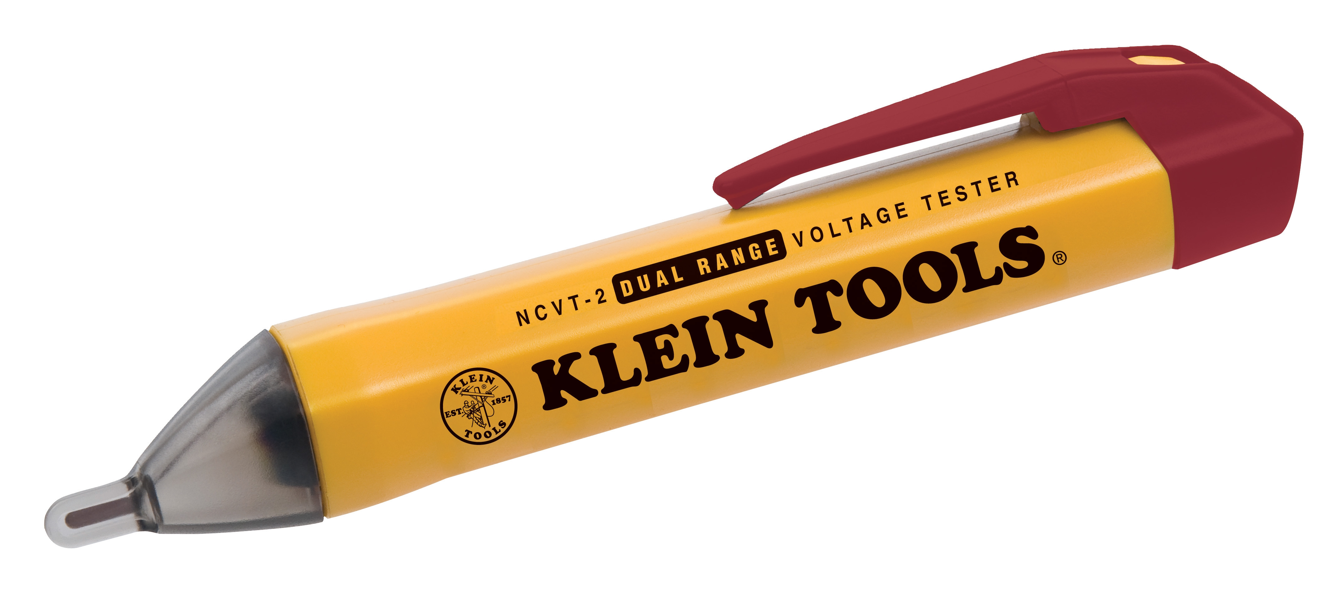
For Non-Contact Voltage Detectors: These instruments detect electrical fields without physical contact, making them essential for safety testing. Common issues include reduced detection range, failure to activate on known live conductors, or false positive activation. Begin by testing the device against a verified live circuit (ideally a functioning outlet or test circuit of known voltage). If the detector fails to respond, the first diagnostic step is battery assessment. Most modern non-contact detectors require 1.5V or higher battery voltage; replacement is straightforward and should be performed according to manufacturer specifications. If battery replacement doesn't restore function, the internal sensor circuitry has likely failed and the unit requires replacement—field repair is not recommended for safety-critical devices.
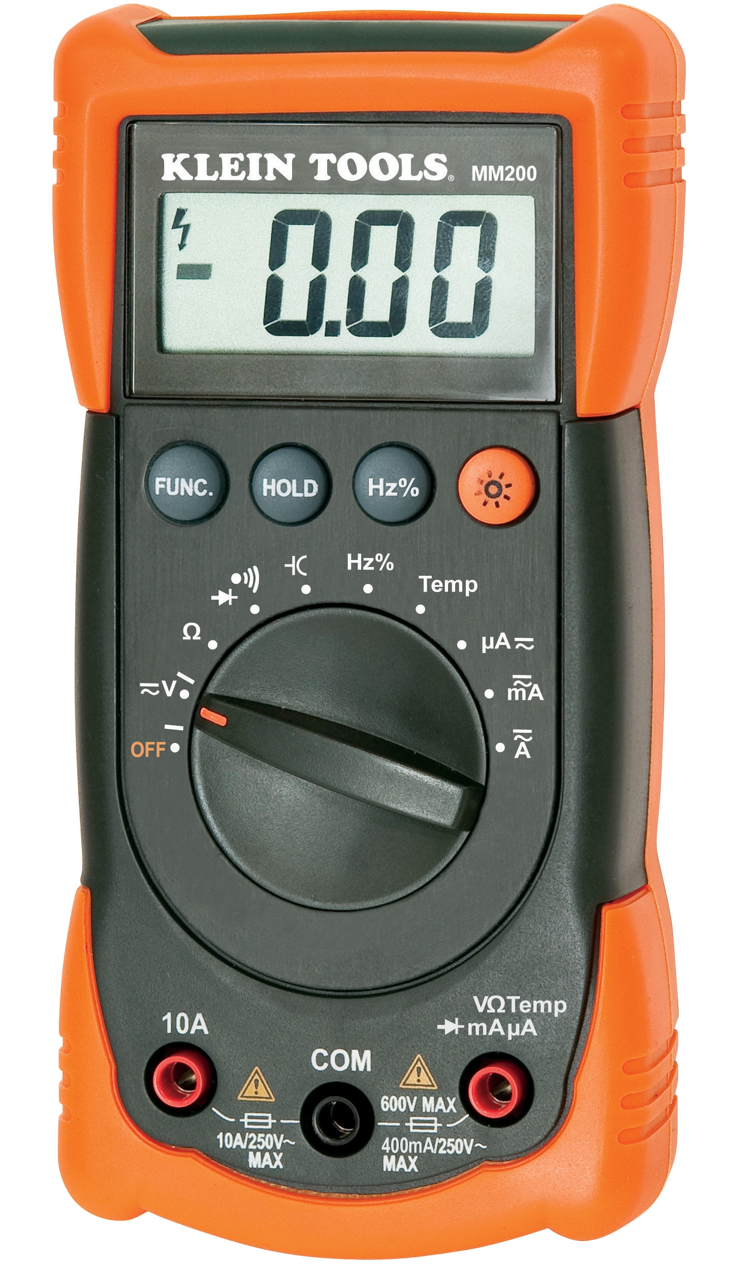
For Digital Multimeters: These versatile instruments measure voltage, current, and resistance across multiple ranges. Troubleshooting depends on failure symptoms. If the display is blank or unresponsive, check battery voltage (typically 9V for standard units). If battery is adequate but display remains inactive, press all buttons systematically to detect stuck controls. If the unit powers on but displays erratic or locked values, disconnect all probes and observe whether the reading changes—a frozen reading with no change indicates circuit failure. For readings that appear inconsistent or drift over time, perform range validation: measure a known voltage source (such as a functioning AA battery at 1.5V) across the lowest voltage range setting. If the reading deviates more than ±3% from the known value, the device has drifted out of calibration and should be serviced by an authorized calibration facility.
For Type K Thermocouples: These temperature sensors function through a thermoelectric junction; measurement failures typically result from junction degradation or open-circuit conditions. To diagnose, disconnect the thermocouple from its measuring instrument and perform a visual inspection of the probe tip. Visible corrosion, discoloration, or separation indicates junction failure. If the junction appears intact, reconnect and test against a known temperature reference (such as ice water at 0°C or boiling water at 100°C). If readings deviate more than ±2°C from known values, the junction has drifted and requires replacement. For high-temperature applications above 500°C, more frequent inspection and replacement intervals (every 12-24 months) are necessary due to accelerated metallurgical degradation.
Real-World Application: Troubleshooting Scenarios in Industrial Settings
Consider a maintenance scenario in a petrochemical facility: technicians are performing electrical safety verification on motor circuits before shutdown. The non-contact voltage detector fails to indicate voltage on a circuit that should be live. Initial reaction is to assume the circuit is de-energized and proceed with maintenance—but this conclusion is dangerous if the detector has failed. The correct diagnostic procedure: test the detector against a verified live source (another known-live circuit or a test bench outlet). If the detector responds to the verified source but not the suspect circuit, the circuit may genuinely be de-energized. If the detector responds to neither, battery or sensor failure is probable and the device must be replaced before continuing electrical work.
In a food manufacturing facility in a humid tropical environment, temperature measurement on a cooling line shows unexpected fluctuations. The technician measures 8°C when the set point is 4°C, with readings drifting 1-2°C per minute. Testing the thermocouple in an ice bath (0°C reference) reveals a 3°C offset. This indicates thermocouple junction degradation. Rather than troubleshooting the measuring instrument, the thermocouple probe itself requires replacement. The facility's high humidity and salt-air exposure (common in coastal regions) accelerated corrosion of the junction, a predictable failure mode in this environment.
In a commercial HVAC maintenance context, a technician uses a digital multimeter to verify control circuit voltage. The display shows 24V but the HVAC unit responds erratically. Testing against a reference battery (1.5V) reveals the multimeter reads 1.8V—a 20% calibration error. The multimeter requires factory calibration service, and temporary measurements using an alternate verified meter should proceed until recalibration is complete.
Selection and Maintenance Best Practices for Electrical Testing Equipment
Proper selection and preventive maintenance dramatically extend instrument life and ensure measurement reliability. When selecting electrical testing equipment, match specifications to your facility's requirements. A multimeter with automatic range selection reduces operator error and suits technicians working across multiple voltage ranges. For high-temperature applications, specify thermocouples rated for your maximum operating temperature plus a 10% safety margin.
Establish preventive maintenance schedules aligned with environmental factors. In standard industrial environments, inspect electrical testers quarterly and replace batteries semi-annually. In tropical or high-humidity environments (such as facilities in Southeast Asia), increase inspection frequency to monthly intervals and replace batteries every 3-4 months. Store equipment in dry conditions with desiccant packets in sealed containers when not in use.
Maintain a calibration log for multimeters and other precision instruments. Schedule professional calibration annually for instruments in regular use, or after any incident of suspected accuracy loss. For non-contact voltage detectors and basic safety testers, functional testing against known sources suffices for routine verification, but replace units showing performance degradation rather than attempt repair.
Document all measurement equipment serial numbers and purchase dates. This enables tracking of instruments approaching end-of-life and supports root-cause analysis when field failures occur. Cross-reference with environmental conditions (temperature, humidity exposure) to identify patterns in failure modes specific to your facility's location and operating conditions.
Closing Recommendation
Electrical testing and measurement equipment represents a critical investment in facility safety and operational reliability. When troubleshooting fails to restore functionality, swift replacement with verified instruments ensures your maintenance team can continue essential safety verification work without compromise. For comprehensive support selecting appropriate electrical testing equipment, understanding application-specific requirements, and establishing maintenance protocols suited to your geographic location and industrial environment, contact the 3G Electric technical team. We maintain extensive inventory of measurement and detection equipment from established manufacturers and provide expert guidance on equipment selection, application, and troubleshooting across all industrial sectors globally.