Understanding Pressure Regulation as a Safety Foundation
In HVAC systems across Southeast Asia, pressure regulation sits at the intersection of performance and safety. Unlike relay-based or integrated controls that manage electrical sequences, pressure control devices directly govern the flow of combustible gas into your burner, making them arguably the most critical safety component in any heating system.
With 35+ years of industrial equipment distribution experience, 3G Electric has observed that pressure-related failures account for approximately 40% of unplanned HVAC shutdowns in the region. These failures typically stem not from component defects, but from misunderstanding pressure characteristics, installation errors, and inadequate commissioning procedures.
Pressure regulation serves three distinct safety functions: (1) maintaining burner stability by preventing flame extinction during pressure fluctuations, (2) protecting downstream components from overpressure damage, and (3) ensuring consistent fuel delivery across varying demand cycles. In tropical Southeast Asian climates with high ambient temperatures and humidity, these functions become even more critical as thermal expansion and moisture ingress create additional pressure variables.
Practical Pressure Range Selection and Climate Considerations
Southeast Asian HVAC contractors often install equipment designed for European or North American conditions, where standard gas pressures center on 20-50 mbar ranges. However, regional variations in gas supply infrastructure, altitude differences across installations, and thermal cycling specific to tropical climates require deliberate pressure strategy.
The SIT Tandem gas block 0837013 operates across a 7-50 mbar pressure range, delivering up to 4.8 m³/h with a 5 mbar pressure drop. This specification is particularly relevant for Southeast Asian applications because it accommodates both low-pressure municipal gas networks common in developed urban areas and higher-pressure LPG supply systems used in industrial estates and rural installations.
When specifying pressure control components, contractors must account for four environmental factors:
Temperature cycling: Daytime ambient temperatures in Singapore, Malaysia, and Indonesia routinely exceed 32°C, while nighttime cooling creates pressure swings of 2-4 mbar in sealed gas lines. Pressure regulators must maintain setpoint accuracy across this range without drift or hunting behavior that destabilizes the flame.
Altitude variations: Regional installations span from sea level in coastal areas to 1,500+ meters in highland regions. Each 100-meter altitude increase reduces atmospheric pressure by approximately 1.25 mbar, directly affecting burner gas pressure calculations and fuel delivery accuracy.
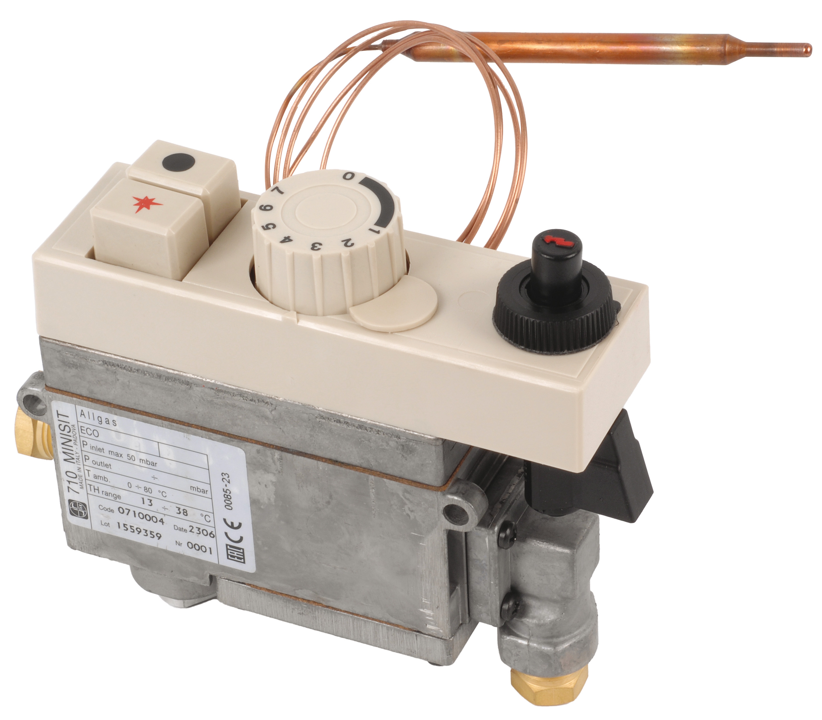
Gas supply quality: LPG and natural gas quality varies significantly across the region. Moisture content, trace sulfur compounds, and pressure volatility from supply sources necessitate robust filter integration and pressure stability margins. The SIT Minisit gas block 0710004 includes integrated thermoelectric safety that compensates for supply quality variations while maintaining pressure regulation.
System demand patterns: Commercial HVAC systems in Southeast Asia typically operate intermittently (2-3 hours daily in office buildings, seasonal patterns in shopping centers). Pressure regulators must respond quickly to demand changes without overshooting, as delayed pressure response causes flame flicker and nuisance safety shutdowns.
Component Selection Matrix: Matching Pressure Control to Application Requirements
Three primary pressure control architectures serve the Southeast Asian HVAC market, each with distinct strengths for specific applications:
Single-function pressure regulation suits straightforward heating applications with stable demand. The SIT Minisit 0710004 combines pressure regulation with thermoelectric safety supervision, making it ideal for small commercial units (3-15 kW) and retrofit installations where space is limited. Its 3.9 m³/h flow rating matches typical air-handling unit burner requirements, and EN 12126 compliance ensures regulatory acceptance across ASEAN nations.
Multifunctional gas blocks integrate pressure regulation, solenoid valve control, and servo-assisted pressure stability for complex systems. The SIT Sigma 0845063 features two automatic solenoid valves and servo-assisted regulation, appropriate for modulating burner systems in large commercial facilities where part-load operation requires precise pressure tracking. The servo mechanism responds to downstream demand signals, automatically adjusting regulator opening to maintain setpoint pressure despite fluctuating inlet pressures—essential for systems fed from variable-pressure LPG networks.
Tandem configuration blocks enable staged burner operation and redundant safety paths. The SIT Tandem 0837013 supports independent control of two gas circuits, permitting staged ignition sequences or allowing one circuit to serve as a redundant backup if the primary circuit pressure drifts. This architecture is increasingly specified in critical facilities (hospitals, data centers, research institutions) where heating system failure creates regulatory compliance risk.
For commissioning decision-making, contractors should evaluate three dimensionless ratios:
- Pressure margin ratio: (Regulator inlet pressure − System operating pressure) / System operating pressure. Maintain >0.4 ratio to ensure stable regulation across temperature swings and supply fluctuations.
- Turndown ratio: Maximum burner flow / Minimum controllable flow. Pressure regulators typically maintain accuracy across 4:1 turndown; systems requiring greater turndown need secondary modulating valves downstream of the main regulator.
- Response time index: Seconds required for pressure to stabilize within ±2% of setpoint after a 20% step change in demand. Southeast Asian humid climates favor regulators with <3 second response time to prevent moisture condensation during prolonged pressure transients.
Commissioning Workflow: Pressure Verification and Safety Validation
The difference between a functioning HVAC system and a reliably safe one often hinges on commissioning rigor. 3G Electric's three-decade experience indicates that approximately 60% of regional HVAC failures trace back to inadequate commissioning procedures—not component defects.
Step 1: Pre-installation pressure survey (2-4 hours)
Before any component installation, contractors should document the actual gas supply pressure at the building entry point across a 7-day measurement period, capturing daily temperature extremes and demand cycles. This empirical data becomes the foundation for all downstream pressure calculations. Use certified digital manometers (±0.1 mbar accuracy minimum) rather than analog gauges, as tropical humidity causes analog pointer stiction and reading errors.
Record three specific data points:
- Peak supply pressure during maximum facility demand (typically early morning)
- Minimum supply pressure during low-demand periods (typically late evening)
- Sustained supply pressure immediately after supply-side pressure regulation adjustments (if present)
Calculate the pressure variance: (Peak − Minimum) / Nominal pressure. If this exceeds 15%, specify a pressure regulator with servo-assisted stability rather than simple spring-loaded designs.
Step 2: Component specification and pressure setpoint definition (3-5 hours)
Using the gas supply survey data, establish three pressure targets:
- Main regulator setpoint: Set 2-3 mbar above the maximum burner design pressure. For a 30 mbar burner requirement, set main regulator to 32-33 mbar.
- Burner inlet pressure tolerance: ±2 mbar from design specification. Pressures exceeding this window cause improper atomization, incomplete combustion, and flame instability.
- Safety shutoff pressure: Typically 1.2× the burner design pressure. At this threshold, pilot safety devices must interrupt fuel supply within 4 seconds to prevent overpressure escalation.
Select components using the pressure margin ratio calculated earlier. If margin ratio falls below 0.3, specify a secondary regulating valve downstream of the main regulator to achieve safe pressure control despite high inlet pressure variability.
Step 3: Installation with pressure monitoring integration
Install pressure monitoring ports on both inlet and outlet sides of every pressure control component. These ports enable field verification during commissioning and ongoing diagnostic monitoring. The SIT Tandem 0837013 and SIT Sigma 0845063 include factory-drilled monitoring ports; retrofit installations require careful tapping to avoid contaminating the gas stream.
Use stainless steel or nylon tubing for monitoring lines; copper tubing corrodes rapidly in tropical humidity and introduces particulate contamination. Isolate monitoring tubes from direct sunlight to prevent thermal errors in pressure measurement.
Step 4: Live pressure commissioning (4-6 hours)
After gas supply confirmation and burner assembly, perform pressurized commissioning in three phases:
Phase 1—Idle pressure stability: With all burners off, verify main regulator outlet pressure remains within ±1 mbar of setpoint for 60 continuous minutes. Pressure drift >1 mbar indicates regulator drift or internal seal degradation requiring component replacement.
Phase 2—Single-stage operation: Energize the pilot and first-stage burner. Measure and record inlet pressure, main regulator outlet pressure, and burner inlet pressure at 5-minute intervals for 30 minutes during steady-state combustion. All pressures should stabilize within the tolerance band established in Step 2. If burner inlet pressure drifts >±2 mbar, trace the cause: (1) gas supply pressure fluctuation, (2) regulator calibration drift, or (3) downstream restriction (water trap, filter clogging).
Phase 3—Demand cycling: Execute 20 consecutive burner on-off cycles at 10-minute intervals. During each transition, photograph pressure gauges or log digital readings at startup (0-5 seconds), stabilization (5-30 seconds), and shutdown (post-flame-out). Pressure overshoot at startup should not exceed 5 mbar above setpoint; pressure undershoot at shutdown should not persist beyond 10 seconds. Deviations indicate regulator response time inadequacy or insufficient outlet line volume (line size too small for flow delivery).
Document all commissioning data and retain for minimum 24 months. In the event of subsequent HVAC malfunction, this historical data enables rapid root-cause isolation and prevents misdiagnosis.
Step 5: Ongoing verification schedule
Establish quarterly pressure verification intervals for systems serving critical facilities, biannual for routine commercial installations. Recheck pressure setpoints, measure response times, and inspect for external leaks or corrosion. Tropical moisture promotes solenoid valve stiction and regulator internal corrosion; preventive inspection every 12 months significantly extends component life and maintains safety performance.
Integration with Burner Control Electronics
Pressure regulation components do not operate in isolation; they interface with burner control electronics that monitor performance and enforce safety interlocks. The SIT 0577211 control box coordinates electronic burner sequencing with mechanical pressure regulation, providing microprocessor-based monitoring that detects pressure anomalies the human operator cannot perceive.
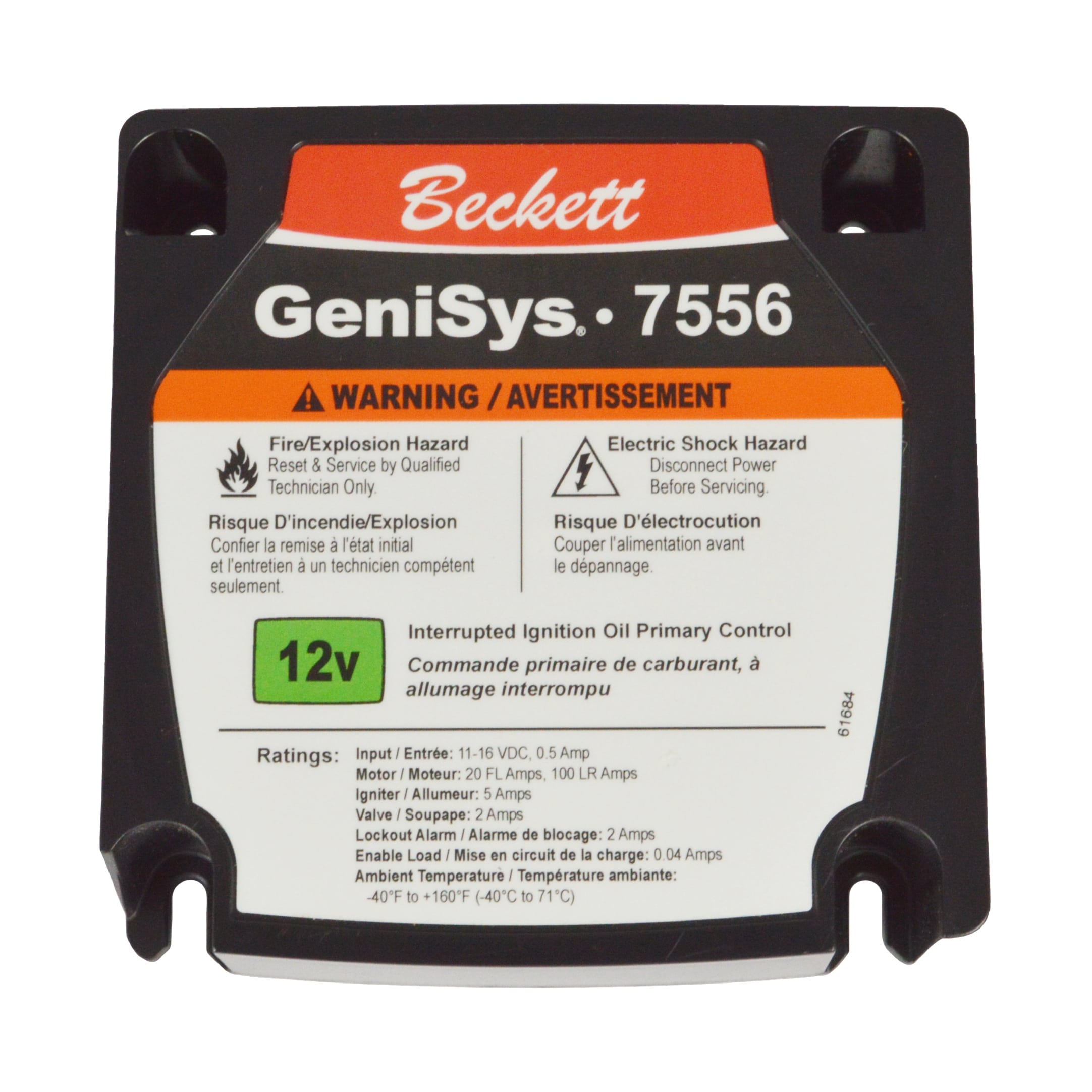
For systems employing oil burners in backup heating configurations, the Beckett GeniSys® 7556 12V Oil Burner Control integrates similar safety monitoring, though with oil-specific flame detection algorithms. If your facility uses dual-fuel HVAC systems (gas primary, oil backup), ensure both control systems share common pressure monitoring thresholds and alarm outputs to prevent safety conflicts during fuel-switching sequences.
The integration strategy should specify:
- Common pressure alarm setpoint (typically 1.2× burner design pressure)
- Unified shutdown sequencing (both gas and oil circuits shut within 2 seconds of pressure alarm)
- Shared flame loss response time (burner must cease fuel delivery within 4 seconds of flame extinction detection)
This harmonization prevents the dangerous condition where one fuel system shuts safely while the other continues running—a scenario that creates uncontrolled pressure escalation and potential rupture.
Regional Compliance and Long-Term Maintenance Strategy
Southeast Asian regulatory frameworks increasingly align with EU safety standards, though implementation and enforcement vary by nation. Singapore, Malaysia, and Indonesia have adopted EN 12126 (gas control requirements) and EN 13611 (burner safety) as compliance baselines. Vietnam and Thailand show similar regulatory momentum.
When specifying pressure control components, confirm ISO/EN certification compliance for the target market. The SIT products referenced throughout this guide carry CE marking and full EN compliance documentation, suitable for installation across ASEAN nations. However, some regional suppliers may offer non-certified variants at lower cost; these create liability risk if system failures occur in regulated environments.
For maintenance continuity, retain component datasheets, calibration certificates, and pressure logs in a centralized digital system. This documentation proves due diligence in the event of regulatory inspection or insurance claim investigation following a heating system incident.
With 35+ years serving the Southeast Asian industrial market, 3G Electric maintains component inventory and technical support specifically positioned to support regional HVAC contractors with pressure control components, commissioning guidance, and troubleshooting resources. Contact our technical team to discuss pressure strategy for your next complex HVAC installation.