Understanding Burner Control System Architecture for Your Plant
Burners and combustion systems depend entirely on reliable control mechanisms to operate safely and efficiently. Unlike generic equipment specifications, control system selection directly impacts your plant's uptime, safety compliance, and operating costs. Over 35 years of supplying industrial equipment across Southeast Asia, 3G Electric has observed that many plant managers inherit burner systems without fully understanding their control architecture—leading to unexpected failures, compliance gaps, and unnecessary maintenance expenses.
A burner control system consists of three integrated functional layers: ignition management, flame supervision, and modulation control. Each layer must be sized appropriately for your specific fuel type, thermal load, and operational mode. The ignition layer handles startup sequences and pilot flame establishment. The flame supervision layer continuously monitors combustion safety using either ultraviolet (UV) or ionization detection. The modulation layer adjusts burner output to match actual demand, preventing overshooting and fuel waste.
Your first critical decision involves determining whether your plant requires a single-fuel or multi-fuel control strategy. Single-fuel systems (gas-only or oil-only) offer simplified control logic and lower component costs. Multi-fuel systems require sophisticated switching logic, separate fuel trains, and dual-sensing flame detection. In Southeast Asia's industrial landscape, where power interruptions and fuel supply volatility are genuine concerns, many plants operate dual-fuel burners as a resilience strategy—but this complexity must be reflected in control system specification.
The Kromschroder Relay BCU 570WC1F1U0K1-E represents a proven control architecture for plants requiring direct ignition with either intermittent or continuous pilot modes. This relay complies with EN 746-2 and EN 676 standards—critical for export-oriented manufacturing and food processing operations subject to European customer audits. For plant managers in Singapore, Malaysia, or Thailand managing ISO 9001 or FSSC 22000 certifications, equipment compliance becomes part of your audit trail and customer documentation requirements.
Pressure Monitoring and Safety Instrumentation in Control Systems
Flame detection alone cannot guarantee combustion safety. Your control system must also monitor fuel pressure, combustion air pressure, and control air pressure (if using pneumatic actuators). Pressure switches serve as the critical boundary condition—they prevent ignition attempts when fuel cannot reach the burner, and they shut down operation if pressure drops unexpectedly during running.
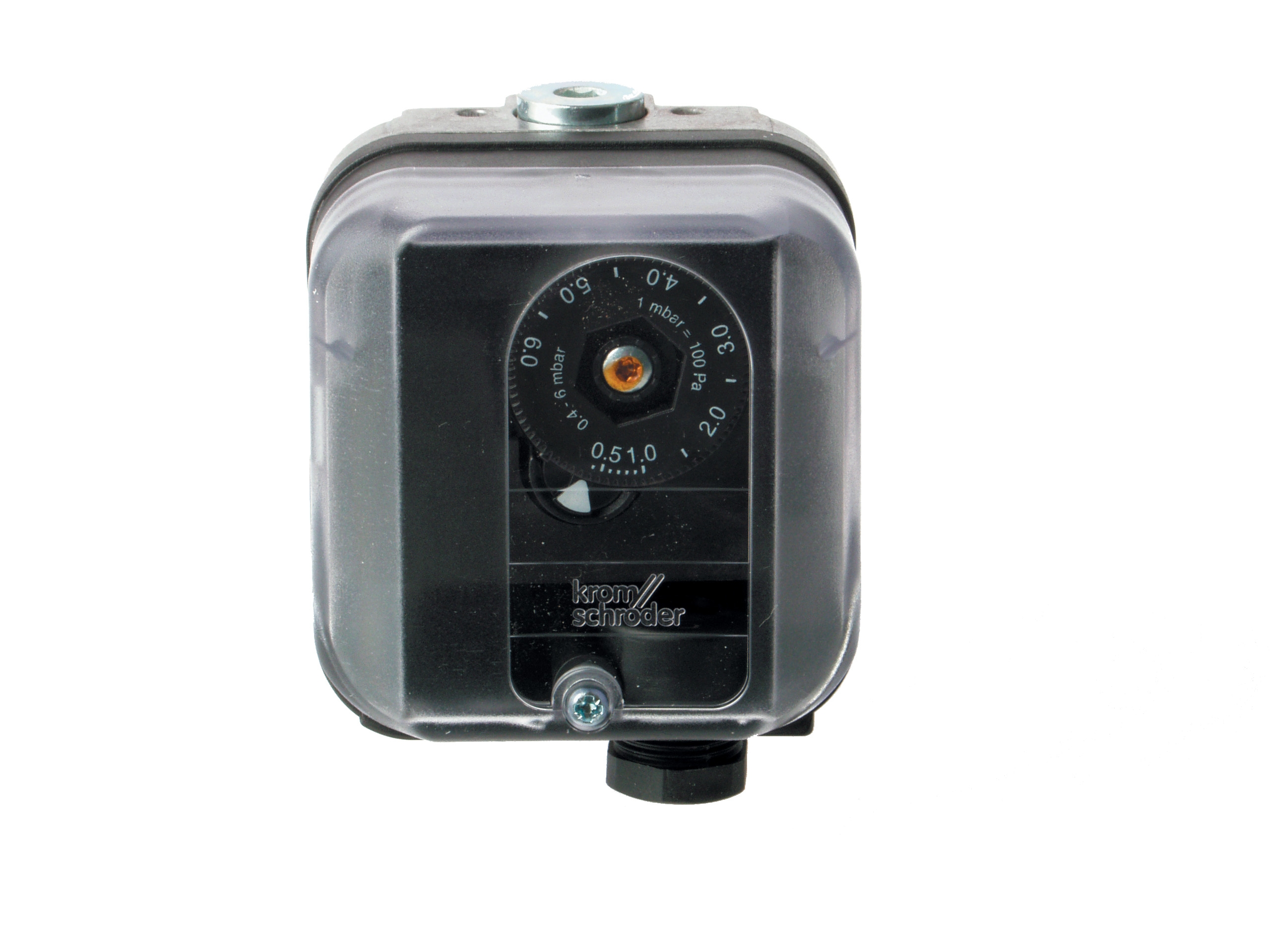
The Kromschroder Pressure Switch DG 50U/6 integrates Safety Integrity Level (SIL) 3 rating with Performance Level e certification. For plant managers unfamiliar with these terms: SIL 3 means the device can be trusted to fail safely in dangerous modes with demonstrated probability of less than one dangerous failure per million hours of operation. This matters directly to your plant's insurance premiums, compliance audits, and operator liability exposure.
During your control system evaluation, specify pressure switches according to three criteria: operating pressure range (must cover your fuel supply variability), response time (typically 50-200 milliseconds for safety functions), and environmental rating. Southeast Asian plant environments often involve high ambient humidity, salt spray (in coastal industrial zones), and aggressive cleaning chemicals. The DG 50U/6's multi-standard certification (FM, UL, AGA, GOST-TR) means replacement parts remain available globally—a practical advantage when your primary supplier faces supply chain delays.
Many plant managers make a costly mistake by oversizing pressure switches. A switch rated for 0-10 bar cannot provide reliable response at 1-2 bar operating pressures. Similarly, switches with excessive hysteresis (pressure differential between opening and closing) can create control instability, especially in modulating burner systems. Your control system design must match switch specifications to actual operating envelope—if your facility operates at 2-4 bar gas pressure, specify a switch rated 0-6 bar with hysteresis under 0.3 bar.
Multi-Fuel Burner Control: Managing Complexity Without Sacrificing Reliability
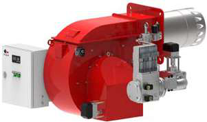
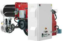
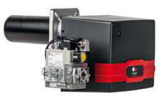
Plants operating heavy oil or dual-fuel burners face fundamentally different control challenges than gas-only operations. The FBR GAS XP 60/2 CE TC EVO serves plants requiring two-stage gas burner control with 116–630 kW thermal power range. The FBR KN 1300/M TL EL, by contrast, represents a dual-fuel heavy oil burner delivering 1700–11500 Mcal/h with modulating control—significantly more complex operationally.
Heavy oil burner control requires active management of fuel viscosity, combustion air preheating, and nozzle atomization pressure. When your plant switches from summer gas operation to winter oil operation, or alternates between fuels based on commodity pricing, the control system must execute a coordinated fuel change-over sequence. This sequence involves: stopping the primary fuel, confirming flame extinction through timed-out flame supervision, pressurizing the secondary fuel train, energizing the ignition system, and resuming combustion on the new fuel.
The Siemens Relay LFL 1.622 provides safety control for exactly this application—it supports gas, oil, or dual-fuel burners with medium to high power ratings. The LFL 1.622 features both UV and ionization flame monitoring capability, allowing your plant to select the most reliable detection method for your specific fuel and combustion characteristics. UV detection performs better on clean gas flames; ionization detection tolerates dusty or sooty combustion conditions better.
For plant managers implementing dual-fuel systems, establish clear operational procedures: designate a primary fuel (typically the more economical and available), define the switching trigger (temperature, fuel availability, or cost threshold), and document the change-over sequence for operator training. 3G Electric recommends commissioning each fuel mode independently before operating in dual-fuel mode. Many operational failures arise because the secondary fuel path was never properly tested at commissioning—operators discover the problem under emergency conditions when switching is required urgently.
Practical Integration: Connecting Control Systems to Your Plant Infrastructure
Control system integration begins with understanding your plant's existing automation level. Some facilities operate entirely manual (operator opens fuel valve, lights burner, monitors flame visually). Others have partial automation (automatic ignition, manual flame monitoring). Modern plants typically require fully automatic control with remote monitoring capability.
When specifying a control system for integration with your plant's existing equipment, map three integration points: the input signals (what sensors feed data into the control relay), the output signals (what the relay commands to your fuel valves, ignition transformer, and dampers), and the communication interface (how the control system reports status to your plant management system).
Your fuel train downstream of the control relay will likely include solenoid shut-off valves, proportional or modulating control valves, and fuel filters. The control system must energize these in correct sequence with appropriate timing. The BCU 570 and LFL 1.622 both integrate these sequences according to European standards—they expect proper fuel train components downstream. If your existing fuel valves are undersized, slow, or prone to sticking, the control relay cannot compensate; you must upgrade the fuel train components.
For combustion air control, assess whether your burner system uses forced draft (electric fan), induced draft (separate exhaust fan), or natural draft. Forced draft systems require damper control (typically pneumatic or electric modulating damper) coordinated with the burner control relay to maintain correct air-fuel ratio across modulation range. If your plant lacks modern combustion air damper control, installing a new burner control system without upgrading the damper mechanism will yield disappointing efficiency results.
A practical integration checklist for plant managers:
- Power supply: Verify adequate 24 VDC supply availability; control relays consume 10-25 watts continuously, plus additional load for solenoid valves and ignition transformer
- Signal integrity: Screen all burner sensor wiring separately from power wiring; use shielded twisted pair for flame detector signals to prevent false flame detection
- Mechanical mounting: Mount the control relay in a panel with ambient temperature 0–50°C; avoid direct sunlight, steam, or dust exposure
- Spares inventory: Stock replacement flame detector electrodes (critical consumable for UV-based systems)
- Commissioning documentation: Retain all test certificates, calibration records, and adjustment settings; these become mandatory compliance evidence during insurance audits
Troubleshooting and Support: Leveraging 35+ Years of Field Experience
When a burner control system fails, the financial impact extends beyond the equipment cost. Unplanned shutdowns stop production, disrupt supply commitments, and expose your plant to customer penalties. Plant managers should establish a support relationship with their equipment supplier before problems occur.
3G Electric's 35-year history in Southeast Asian industrial equipment distribution has yielded deep field expertise in burner system diagnostics. Common control system failures we encounter include: false flame signals (typically UV sensor contamination or ionization electrode wear), fuel valve sticking during the ignition sequence, and modulation instability caused by control loop tuning errors.
False flame signals represent the most frequent complaint. If your control system cycles repeatedly (ignites, detects flame, then re-ignites after a few seconds), the most likely causes are: UV sensor window contamination, ionization electrode gap adjustment, or interference from the ignition transformer energy (electrical coupling into the flame detector circuit). UV sensors require annual cleaning in dusty plant environments; ionization electrodes require gap re-setting if flame detection becomes unreliable.
Fuel valve sticking typically occurs when fuel contaminants accumulate in the valve spool (particularly common with heavy oil burners in plants with marginal fuel filtration). Prevention requires maintaining fuel filter pressure drop monitoring; when differential pressure approaches 1 bar, change the filter element before valve stiction occurs.
Modulation instability manifests as hunting behavior—the burner continuously increases and decreases output around the setpoint. This usually indicates incorrect tuning of the control loop's proportional-integral (PI) parameters, or a mechanically binding damper. Never attempt to retune control parameters without formal training; incorrect adjustments can create unstable conditions that damage equipment.
Your plant should maintain emergency contact with your burner equipment supplier and control system provider. Both the Kromschroder and Siemens control relays can be diagnosed through visual inspection of LED status indicators on the relay front panel—learn to interpret these signals so you can communicate accurately with technical support when failures occur.