Burner Control System Diagnostics: Troubleshooting Flame Detection & Safety Relay Failures in Singapore Industrial Applications
Industrial burner control systems are the backbone of safe, efficient combustion across Singapore's manufacturing, processing, and energy sectors. Yet despite their critical role, many procurement and maintenance engineers lack a structured approach to diagnosing control system failures—particularly around flame detection and safety relay operation. This article bridges that gap by providing a technical framework for identifying common control system faults, understanding root causes, and implementing corrective actions. Whether you're managing a process plant, coordinating equipment maintenance, or selecting replacement control components, this guide equips you with the diagnostic knowledge needed to minimize downtime and ensure safe burner operation.
Understanding Burner Control System Architecture & Flame Detection Logic
A modern industrial burner control system operates as an integrated safety-critical circuit. The control relay receives inputs from multiple sources—ignition commands, flame sensors, pressure switches, and manual reset buttons—and orchestrates a sequence of events: fan pre-purge, fuel valve energization, ignition spark, and flame detection confirmation. If the flame sensor fails to detect flame within the programmed detection window (typically 3–5 seconds), the control system enters a lockout state and de-energizes the fuel valve immediately.
Flame detection in modern burners relies on two primary technologies: infrared flame cells (which sense radiant energy from the flame) and photoresistive or phototransistor flame sensors (which respond to specific light wavelengths). The choice of sensor technology depends on the burner type, fuel category, and ambient conditions. For oil and biomass burners, blue-flame photocells are standard; for gas burners operating in high ambient light, infrared sensors offer superior rejection of false signals.
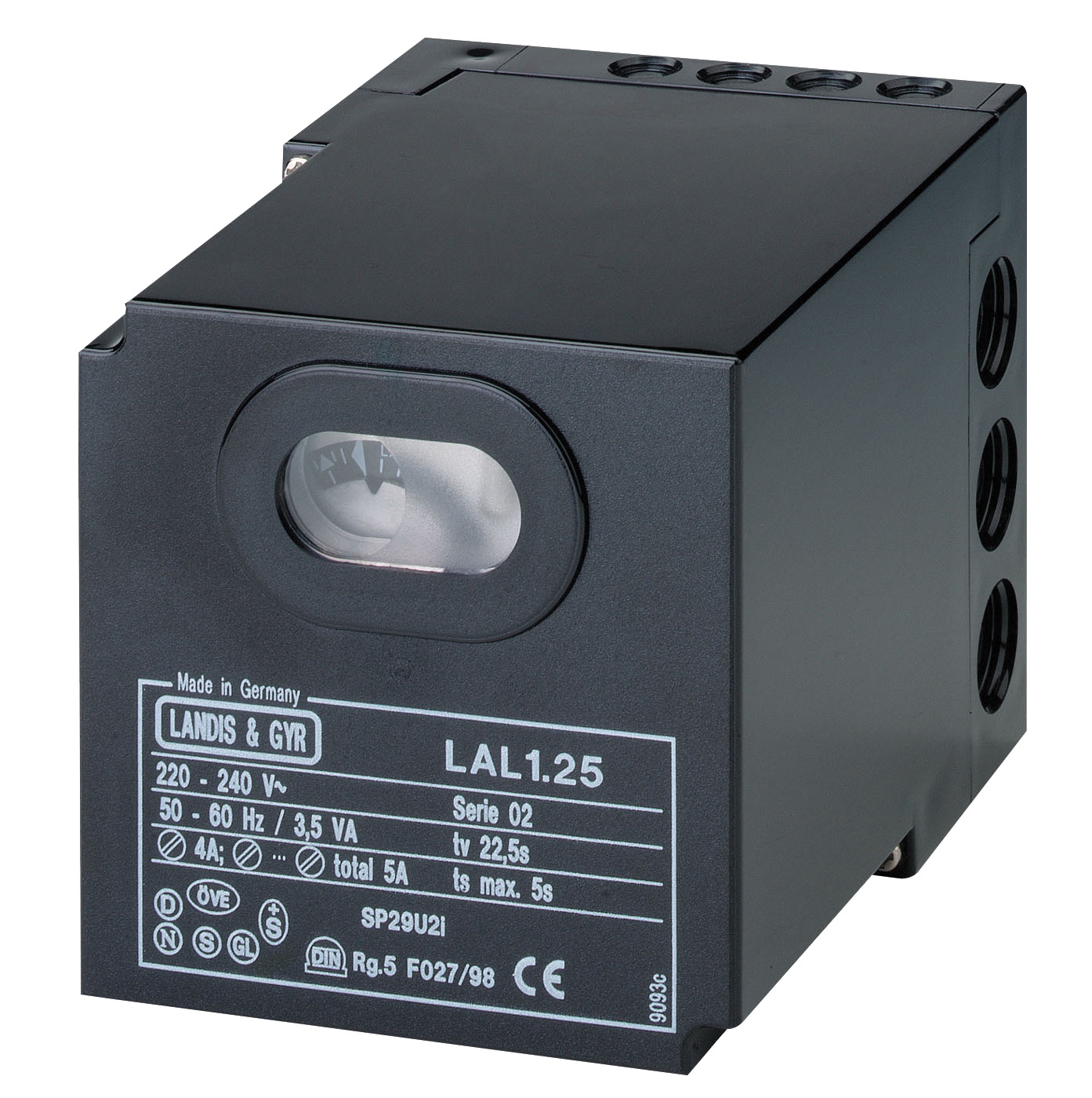
The control relay itself—whether a standalone unit or modular base-mounted assembly—performs continuous self-diagnostics during operation. Modern safety relays incorporate non-volatile memory to lock out the burner after a failed ignition sequence, preventing dangerous accumulation of unburned fuel in the combustion chamber. This lockout can only be reset manually, a design principle that protects operators and plant equipment.
Understanding this architecture is essential: a single failure in the flame sensor, wiring, or relay can trigger a complete system shutdown. The diagnostic challenge is isolating which component has failed and determining whether replacement or recalibration is required.
Diagnosing Flame Sensor & Flame Detection Circuit Failures
Flame sensor faults account for approximately 40–50% of burner control system failures in industrial settings. The primary symptoms include repeated lockouts during normal operation, inability to establish flame even when fuel is present, or erratic behavior where the burner fires briefly then shuts down. Diagnosing these issues requires a systematic three-step approach: visual inspection, electrical continuity testing, and signal output verification.
Step 1: Visual Inspection & Optical Condition
Remove the flame sensor from the burner and examine its optical window. Soot accumulation, carbon deposits, and water condensation are the leading causes of sensor blindness. A contaminated infrared cell or photoresistor cannot generate sufficient signal current to activate the control relay. Clean the optical surface gently with a soft, lint-free cloth and a small amount of isopropyl alcohol. Do not use abrasive materials or excessive solvents that may damage the sensor element.
Step 2: Electrical Continuity & Resistance Measurement
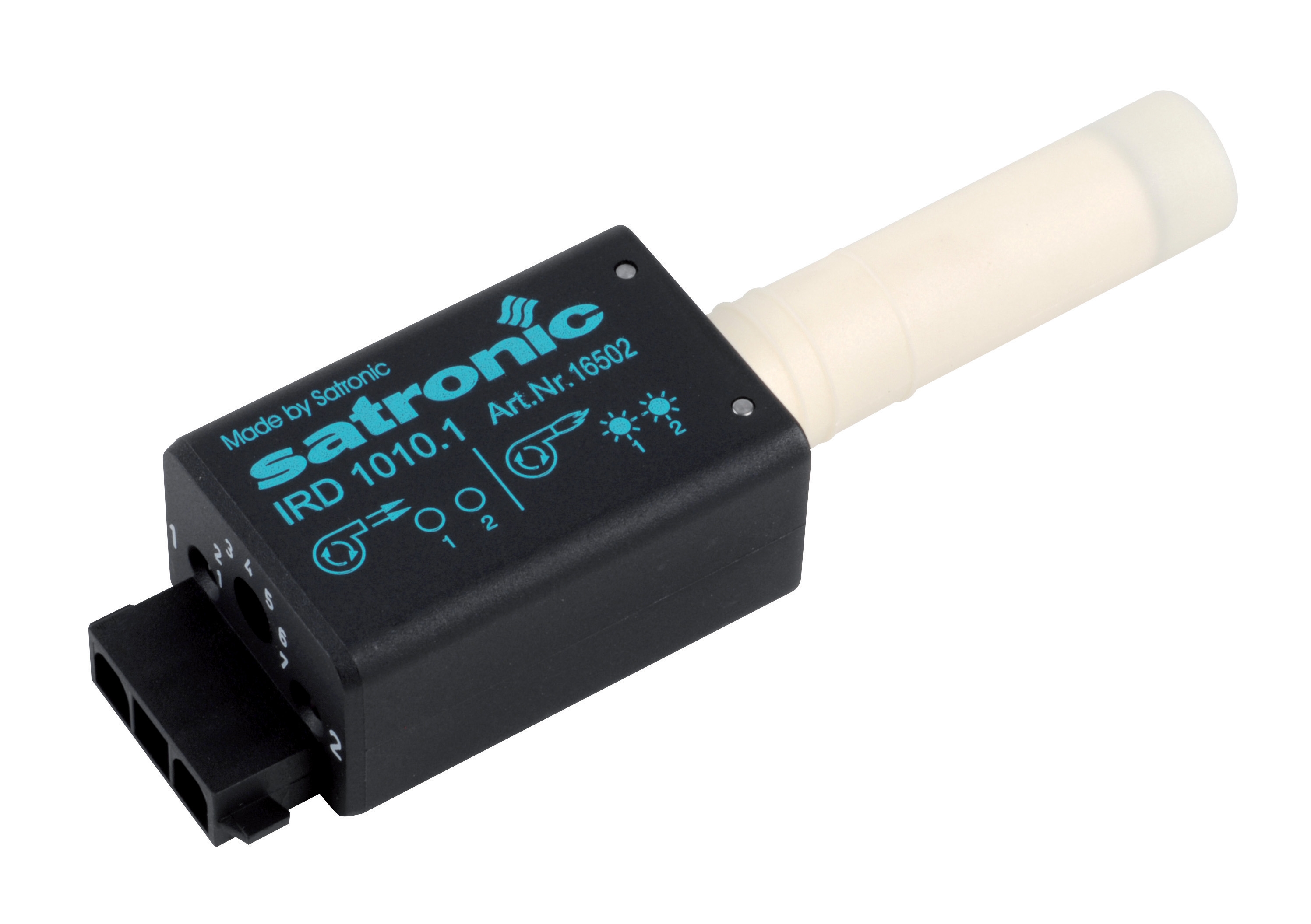
Using a calibrated multimeter, measure the resistance of the flame sensor element. For infrared flame detection cells such as the CBM IRD 1010, typical resistance values should be 20–100 MΩ (megaohms) in darkness and drop to 5–20 MΩ when exposed to flame simulation. If resistance is either extremely high (indicating an open circuit) or near zero (indicating a short), the sensor element has failed and replacement is necessary.
Check the wiring harness continuity from the sensor to the control relay terminals. Corrosion, thermal cycling, and vibration commonly damage connectors in harsh industrial environments. A corroded connection may show intermittent continuity—registering continuity in some measurements but not others.
Step 3: Signal Output & Control Relay Response
With the sensor connected to the control relay, apply a controlled flame stimulus (typically a lit burner test or a laboratory flame source) near the sensor. Monitor the control relay for a confirmation signal—usually an audible click or a light-emitting diode indicator. If the relay does not respond to flame stimulus despite confirmed sensor resistance within range, the relay's flame detection circuit may be at fault. This requires relay replacement rather than sensor replacement.
Safety relays such as the CBM Relay LAL 2.14 incorporate hardwired flame detection logic; if the detection amplifier fails internally, no amount of sensor cleaning will restore function. Document the test results—this data becomes crucial when communicating with your equipment supplier or maintenance contractor.
Safety Relay Lockout Diagnosis & Control System Reset Procedures
When a burner enters lockout, the safety relay remains de-energized until the lockout condition is manually cleared. This is intentional: lockout prevents automatic restart after a failed ignition sequence, protecting personnel and plant equipment from fuel accumulation hazards. However, frequent lockouts indicate an underlying problem that must be resolved before permanent operation can resume.
Identifying Lockout Causes
Lockout is triggered by one of five primary conditions: (1) failure to detect flame within the detection window, (2) loss of electrical supply to the control relay, (3) activation of a safety interlock (such as a pressure switch or limit thermostat), (4) manual reset button activation, or (5) internal relay fault detected by self-diagnostic circuitry.
Start by verifying the ignition sequence. Does the burner ignitor spark visibly? Is fuel reaching the combustion head? On gas burners, check gas supply pressure at the inlet: modern gas burners like the FBR GAS X5 require minimum inlet pressures of 27–33 mbar (depending on gas type), measured at the control valve inlet. Insufficient pressure is a frequent cause of weak ignition and failed flame establishment.
Next, verify all interlock switches. On forced-draft burners, confirm that the air pressure switch closes when the fan reaches operating speed. On modulating systems, verify that the control probe signal is within specification. Defective interlocks that remain open will prevent fuel valve energization entirely, simulating a flame detection failure.
Manual Reset & Restart Procedures
Most industrial safety relays feature a manual reset button (often a large red button on the relay housing). After confirming that the underlying fault is resolved—flame sensor cleaned, fuel pressure restored, or interlock switch repaired—press the reset button once. The relay should de-latch, re-energizing the fuel valve and allowing the burner to attempt ignition again. If the burner locks out immediately after reset, do not continue attempting restarts; instead, remove power, wait 30 seconds, and investigate further. Repeated reset attempts without correcting the root cause waste fuel and delay proper diagnosis.
For complex control systems with multiple safety relays or modulating controls—such as CBM Relay SM 592.2 units—consult the system wiring diagram to identify which relay has locked out. Some systems incorporate multiple flame detection circuits or redundant safety switches; a fault in one circuit may not immediately shut down the entire burner.
Real-World Diagnostics: Case Scenarios from Singapore Industrial Applications
Scenario 1: Intermittent Lockout on a Modulating Gas Burner
A chemical processing facility in Singapore's Jurong industrial zone experiences burner lockouts every 20–30 minutes during normal heating operation. The burner uses a modulating control system with an optional CBM Base for GE 733 integrated with a flame detection cell. The maintenance team reports that the burner fires reliably during startup but then randomly enters lockout. Diagnosis: The control probe (temperature sensor) is drifting, causing the modulation system to misinterpret steady-state conditions as flame loss. Solution: Recalibrate the probe or replace it with a factory-matched unit. This is a control circuit fault, not a flame sensor failure, and only becomes apparent during extended operation when thermal drift accumulates.
Scenario 2: Cold-Start Ignition Failure in High-Humidity Environment
A marine terminal in Singapore's port authority experiences burner ignition failures during early-morning operations when humidity is highest. The flame sensor—a photoresistive cell—functions normally during daytime but fails to detect flame at dawn. Root cause: Moisture condensation on the sensor optical window during the cool night. The high humidity combined with thermal cycling causes water to form a thin film on the sensor element, blocking infrared light transmission. Solution: Install a heated sensor housing or a protective optical purge (pressurized air flowing across the sensor window) to prevent condensation. This prevents the fault rather than chasing repeated sensor replacements.
Scenario 3: Relay Failure After Electrical Transient
An industrial bakery experiences a sudden, complete system failure: multiple burners entering lockout simultaneously after a brief power fluctuation (possibly a utility brownout or on-site generator switchover). The flame sensors test normal, gas supply pressure is correct, and interlocks are functional. Diagnosis: The safety relays themselves have been damaged by electrical transient overvoltage, a common occurrence in facilities with large motor loads or aging electrical infrastructure. The control circuits are internally damaged but may not show obvious external signs. Solution: Replace affected relays with new units, and consider installing surge protection (varistor-based suppression modules or dedicated transient voltage suppressors) on the control circuit input.
Selection & Replacement Criteria for Control Components
When a diagnosis confirms that a control relay or flame sensor requires replacement, procurement engineers must ensure that the replacement unit matches the original specification exactly. Burner control systems are tightly integrated; substituting an incompatible relay or sensor may prevent ignition, create false flame signals, or compromise safety interlocks.
Key Specification Matching Points:
• Fuel type: Natural gas, LPG, or oil burners require different flame detection technology and relay configurations. Gas relays cannot be used on oil burners and vice versa.
• Flame detection method: Infrared, blue-flame photocell, or photoresistor. The sensor type must be approved for your specific burner model and fuel category.
• Voltage & frequency: European control relays are typically 230V AC 50Hz; some units accept 110–240V, but always verify before ordering.
• Modulation capability: If your burner includes optional modulation, the control relay must support proportional or PID modulation commands; standard on/off relays are incompatible.
• Safety certification: Confirm that replacement relays and sensors carry CE marking or equivalent certification required in Singapore (typically IEC 61508 functional safety standards for oil burners, EN 60730 for gas appliances).
Consulting original equipment documentation or reaching out to your experienced equipment supplier—such as 3G Electric—ensures that replacements are correct the first time, avoiding costly second-site visits and extended downtime.
Closing & Next Steps
Flame detection and control relay failures are manageable when approached systematically. By mastering visual inspection, electrical testing, and logical troubleshooting sequences, procurement and maintenance engineers can reduce mean time to repair and improve overall plant reliability. The key is understanding that burner control systems are safety-critical: any diagnosis should prioritize safe shutdown over continuous operation, and any repairs should be verified before returning the burner to full-load service.
For detailed technical specifications, wiring diagrams, or diagnostic support for specific burner models and control relays in your facility, contact 3G Electric's technical team. As Singapore's experienced industrial equipment distributor since 1990, we maintain extensive product knowledge and can help you source exact-match replacement components or recommend system upgrades to enhance reliability and safety. Visit our burners & combustion product range or speak with our engineers to discuss your diagnostic findings and next steps.