Burner Control Relay Selection and Commissioning: A Technical Guide for Global Industrial Maintenance Teams
Burner control relays form the electronic logic foundation of modern combustion safety systems. Unlike individual flame sensors or thermocouple devices, control relays integrate multiple safety functions—flame supervision, ignition sequencing, pressure regulation, and fault detection—into a single modular unit. For maintenance teams and service engineers operating across diverse industrial applications globally, understanding relay architecture, selection criteria, and commissioning procedures is essential for system reliability and regulatory compliance. This guide addresses the technical layer between sensor input and burner command output, providing practical reference data and step-by-step procedures for relay-based control system installation and troubleshooting.
Understanding Burner Control Relay Architecture and Function
Burner control relays operate as the decision-making intelligence between detection devices and ignition/fuel supply components. These relays receive input signals from flame sensors, pressure switches, thermostats, and safety interlocks, then output commands to solenoid valves, ignition transformers, and fuel pumps based on programmed sequencing logic.
Modern relay systems employ non-volatile lock-out logic, meaning that if a fault condition occurs—such as flame loss during operation or ignition failure—the relay enters a secure shutdown state that cannot be overridden by manual restart alone. This prevents uncontrolled fuel discharge and aligns with EN 126 (multifunctional gas control devices) and EN 267 (oil burner controls) standards applied globally.
The relay's internal architecture typically includes:
- Input conditioning stage: Amplifies and filters signals from flame sensors or thermocouples, typically operating at millivolt levels (5–50 mV for thermocouples, or photoelectric cell outputs ranging 0–10V)
- Logic processing unit: Executes timing sequences, safety interlocks, and fault detection algorithms with response times typically under 5 seconds
- Output drive circuits: Energize solenoid valves and ignition transformers, with current-carrying capacity ranging 2–10 amperes depending on relay class
- Self-diagnostic capability: Monitors circuit continuity and component health, automatically triggering lock-out if internal faults are detected
Control relays are classified by fuel type and burner configuration. Gas burner relays (such as CM and SM series systems) are optimized for atmospheric and fan-assisted burners with rapid response to ignition demand. Oil burner relays (GR1 series) accommodate slower flame establishment and employ infrared flame detection. Forced-draught gas systems (VM series) require specialized relay logic for draft monitoring and fuel air ratio control. Understanding these distinctions is critical for correct relay selection and prevents installation of incompatible devices.
Relay Types, Technical Specifications, and Product Selection
The global market offers several control relay families, each optimized for specific applications and fuel types. Selection requires matching relay class, fuel type, burner configuration, and electrical specifications to system requirements.
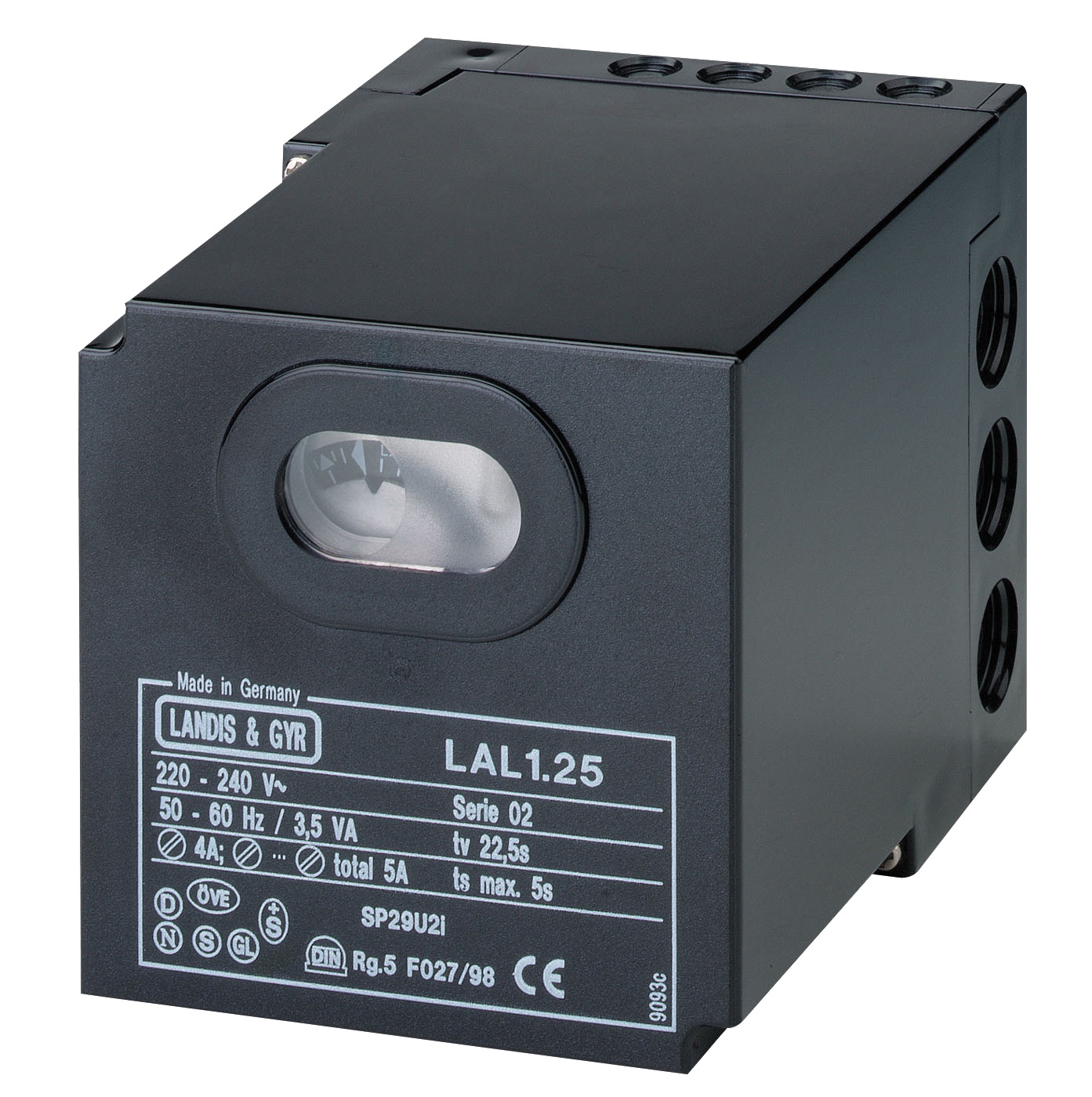
Gas Burner Relay Systems (Atmospheric and Fan-Assisted): The CBM Relay CM391.2 30.5 1.2 represents the EUROBOX series designed for atmospheric and fan-assisted burners operating intermittently. These relays integrate a 30-second pre-purge cycle, flame supervision via photoelectric cell or blue-flame probe, and automatic reset capability following safe shutdown. Key specifications include 220-240V AC operation, 50/60 Hz compatibility, and non-volatile lock-out upon flame loss. The CBM Relay SM 592.2 TW1.5/TS10 extends this platform with enhanced modulation capability, permitting two-stage or proportional burner control for efficiency optimization in large boiler systems.
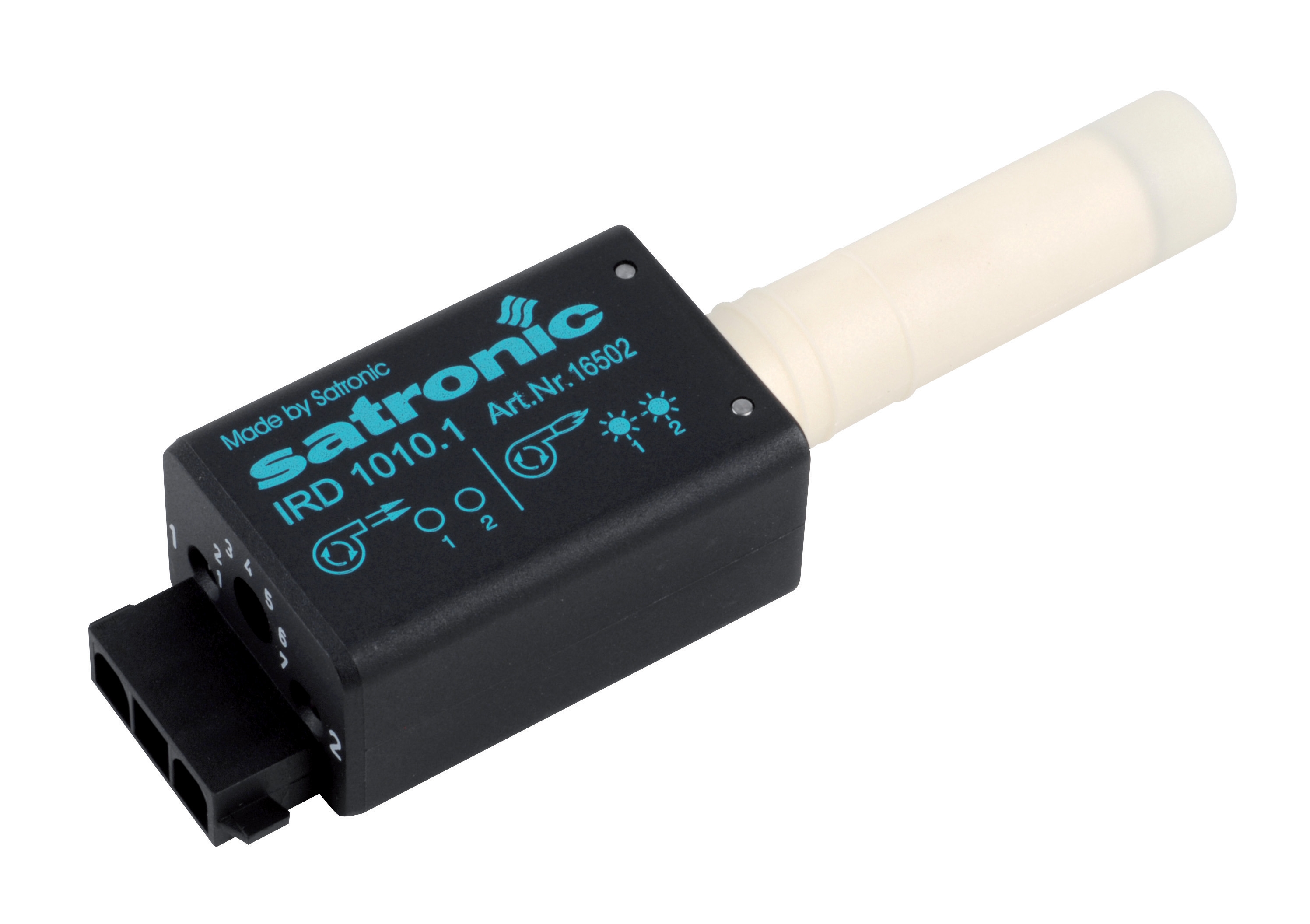
Oil Burner Control Relays: The CBM Relay GR1 10.10 (EURO-OIL series) controls monobloc oil burners, power washers, warm-air generators, and steam boilers. This relay accepts input from infrared flame sensors such as the CBM IRD 1010 blue cell, which detects flickering flame signatures between 2–30 Hz—the characteristic frequency range of oil flames. The GR1 relay incorporates a 3-second ignition guard time, preventing false lock-outs from transient electrical noise, and provides two independent output contacts for staged fuel control.
Forced-Draught Gas Systems: The CBM Relay VM 41 TW30/TS3 (EUROGAS series) is specifically engineered for forced-draught burners operating on gaseous fuels. These systems require continuous monitoring of air pressure (via manometer or differential pressure switch) to ensure proper fuel-air ratios. The VM41 integrates air pressure supervision, adjustable ignition sequence timing (TW30 = 30-second warm-up before flame ignition demand; TS3 = 3-second flame supervision window), and proportional fuel control for efficiency across turndown ratios up to 10:1.
Multifunctional Gas Blocks: For applications requiring integrated pressure regulation, temperature control, and thermoelectric flame supervision in a single device, the CBM Minisit gas block 0710750 consolidates these functions per EN 126 standards. This device is suitable for stoves, boilers, and catering equipment, eliminating the need for separate pilot burner assemblies and reducing overall control cabinet complexity.
Relay selection also depends on electrical supply: 220V single-phase systems are standard globally, but some installations require 110V (Americas) or 380V three-phase supplies. Verify supply voltage and frequency specifications before ordering to prevent installation delays.
Step-by-Step Relay Installation and Commissioning Procedure
1. Pre-Installation Inspection
Before mounting the relay, verify that the electrical supply matches relay specifications (voltage, frequency, earthing). Inspect the relay socket or base—such as the CBM Base for GE 733—for cleanliness and correct pin alignment. Contamination in relay sockets commonly causes intermittent operation and false fault signals.
2. Connect Input Signals
Connect flame sensor leads (thermocouple, photoelectric cell, or infrared detector) to the designated relay input terminals. Verify polarity and shielding: thermocouples generate extremely low voltage (5–50 mV) and require twisted-pair cable with foil shielding grounded at one end only to prevent ground loops. Oil burner cells and blue-flame probes require specific impedance-matched input circuits; consult the relay datasheet for pin assignments.
3. Program Timing Parameters
Most modern relays include adjustable timing parameters. For gas burners, set pre-purge duration (typically 30–60 seconds), ignition guard time (3–10 seconds), and flame supervision timeout (typically 5–10 seconds). For oil burners, the ignition guard time is critical: too short (under 2 seconds) risks false lock-outs; too long (over 5 seconds) permits uncontrolled fuel accumulation during ignition failure.
4. Safety Interlock Verification
Test all safety interlocks: thermostat demand, high-limit cutout, air flow switch (for forced-draught systems), and manual reset switches. Verify that the relay correctly responds to each interlock by entering safe shutdown when any safety switch is opened.
5. Flame Signal Strength Test
With the burner operating at steady state, measure flame signal strength at the relay input using a calibrated millivoltmeter (for thermocouple) or optical power meter (for photoelectric cells). Typical thermocouple signals range 10–25 mV; photoelectric cells should deliver 3–8V DC. Weak flame signals lead to nuisance lock-outs during burner operation; if signal is marginal, reposition the sensor or verify flame quality.
6. Lock-Out Verification
Simulate flame loss by blocking the sensor or interrupting the ignition supply. The relay must enter lock-out within 5 seconds and remain locked until manually reset via the designated reset button or procedure. This confirms non-volatile lock-out logic is functioning correctly.
Relay Selection Criteria and Best Practices for Global Installations
Matching Relay Class to Application
Select relay class based on burner type (atmospheric, fan-assisted, or forced-draught), fuel (gas or oil), and operational mode (intermittent or continuous). Using a gas relay on an oil burner or vice versa results in incompatible flame detection logic and safety failures. Consult equipment nameplates and original control documentation before purchasing replacement relays.
Account for Environmental Conditions
Industrial environments vary globally: tropical regions (Southeast Asia) experience high humidity and corrosive salt spray; arid regions (Middle East, North Africa) present dust ingestion risks; temperate zones may expose relays to temperature extremes. All CBM relays are rated for standard industrial environments (0–50°C ambient, <90% relative humidity, IP54 enclosure rating). In harsh environments, ensure relay mounting in sealed control cabinets with forced ventilation or IP65 rated enclosures.
Verify Regulatory Compliance
Burner control relays must comply with EN 126 (gas) or EN 267 (oil) standards minimum. Some jurisdictions enforce additional requirements: Canada and the USA mandate CSA or UL certification; the EU requires CE marking with documented conformity assessment. Verify certification status before installation in regulated markets.
Plan for Preventive Maintenance
Establish a predictive maintenance schedule: inspect relay cooling (ensure no dust blockage on ventilation slots), verify ignition continuity annually, and test lock-out logic semi-annually. Keep spare relays of each type in stock to minimize downtime during failures. Document all service records to demonstrate regulatory compliance during inspections.
Conclusion and Next Steps
Burner control relays are precision devices requiring careful selection, installation, and commissioning to ensure safe, reliable combustion control across global industrial applications. By understanding relay architecture, matching device class to application, and following systematic commissioning procedures, maintenance teams significantly reduce nuisance shutdowns, extend equipment life, and maintain regulatory compliance.
The product range outlined in this guide—from gas control systems to oil burner relays—represents proven technologies validated across thousands of industrial installations worldwide. If you need assistance selecting the correct relay for your specific application, require technical documentation, or have commissioning questions, contact the technical support team at 3G Electric. Our industrial equipment specialists have served customers since 1990 and maintain inventory of replacement relays, bases, and compatibility adapters for rapid installation globally.