Burner Control Relay Lockout and Reset Failures: Troubleshooting Guide for Industrial Controls & Safety
Burner control relays are critical safety components in industrial combustion systems, designed to protect equipment and personnel by interrupting fuel supply when operational faults are detected. When a control relay enters lockout mode—a non-volatile safety state—it requires manual intervention to reset and restore operation. Understanding the causes of unexpected lockouts and developing systematic diagnostic procedures is essential for maintenance teams and service engineers managing intermittent operation burner systems worldwide.
Understanding Burner Control Relay Lockout Mechanisms and Safety Functions
Burner control relays function as the intelligent brain of a combustion system, continuously monitoring flame presence, pressure conditions, and electrical safety circuits. Most industrial relays, including the Brahma Relay CM 31 TW30/TS10 and Brahma Relay CM 11F TW1.5/TS10, incorporate non-volatile lockout technology. This means that when the relay detects a safety fault—such as flame loss, ignition failure, or pressure anomalies—it immediately cuts power to the gas solenoid valve and enters a protected state that cannot be overridden by simply cycling system power.
The non-volatile lockout serves a critical safety purpose: it prevents automatic reignition attempts that could create dangerous fuel accumulation. Without this protection, a faulty burner might repeatedly try to ignite, flooding the combustion chamber with unburned fuel. The relay holds this lockout state until a technician manually resets it, confirming that the underlying fault has been corrected.
Different relay models employ slightly different safety architectures. The Kromschroder BCU 570WC1F1U0K1-E supports both direct ignition and intermittent or continuous pilot ignition modes, while the Siemens LFL 1.622 provides dual-sensor flame monitoring using both UV and ionization probes. The Siemens LMO 64 is specifically designed for oil burner applications with QRB yellow-flame or QRC blue-flame detection. Understanding which relay model is installed and its specific safety logic is the first step in effective troubleshooting.
Intermittent operation systems—where the burner fires on demand rather than running continuously—place additional stress on control relays because they must reliably ignite and detect flame in rapid succession, sometimes dozens of times daily. Each ignition cycle tests the relay's solid-state circuitry, ignition device, and safety contacts.
Technical Fault Codes and Diagnostic Indicators in Modern Control Relays
Modern burner control relays communicate faults through LED indicators, audible signals, or integration with building management systems. When diagnosing lockout failures, maintenance teams must first understand what the relay is actually telling them. The Brahma CM 31 and Brahma CM 11F both feature high-efficiency solid-state ignition devices and two independent safety contacts in series on the gas valve output—meaning both contacts must close for gas to flow, providing redundant safety logic.
The most common lockout trigger is loss of flame during the ignition sequence or during the safety-proving period immediately after ignition. This occurs when the flame sensor—whether a UV probe, ionization electrode, or infrared detector—fails to confirm that a stable flame exists within the expected timeframe. The Siemens Cell QRB4B-B050B70A yellow-flame sensor is widely used for oil burner applications and must maintain clear optical path to the flame. Soot accumulation, lens fouling, or misalignment will cause flame detection failure and trigger immediate lockout.
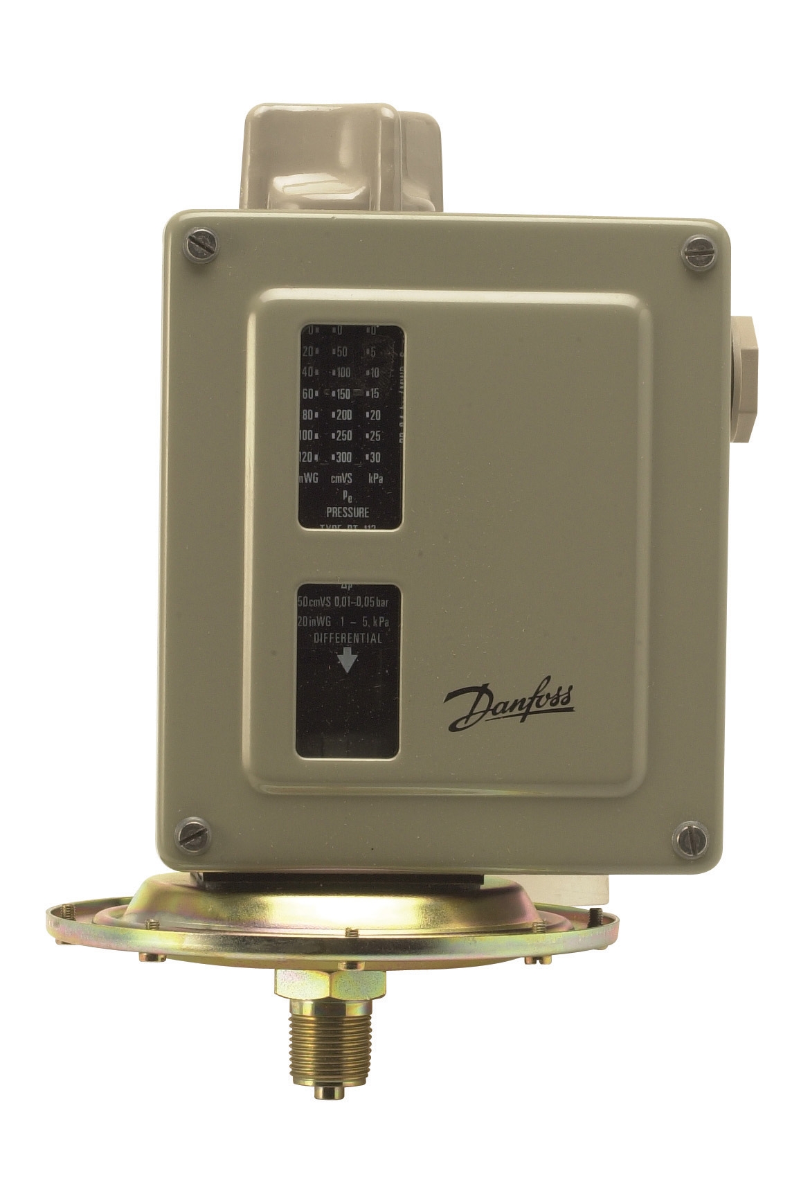
Pressure-related lockouts occur when safety pressure switches detect anomalous conditions. The Danfoss Pressure Switch RT 5 and Kromschroder DG 50U/6 are precision instruments that switch electrical contacts at specific pressure thresholds. A DG 50U/6 operating at SIL 3 / Performance Level e certification means it has passed rigorous testing for systematic safety and random hardware failures. When pressure switches trigger unexpectedly, the relay interprets this as a safety violation and locks out immediately.
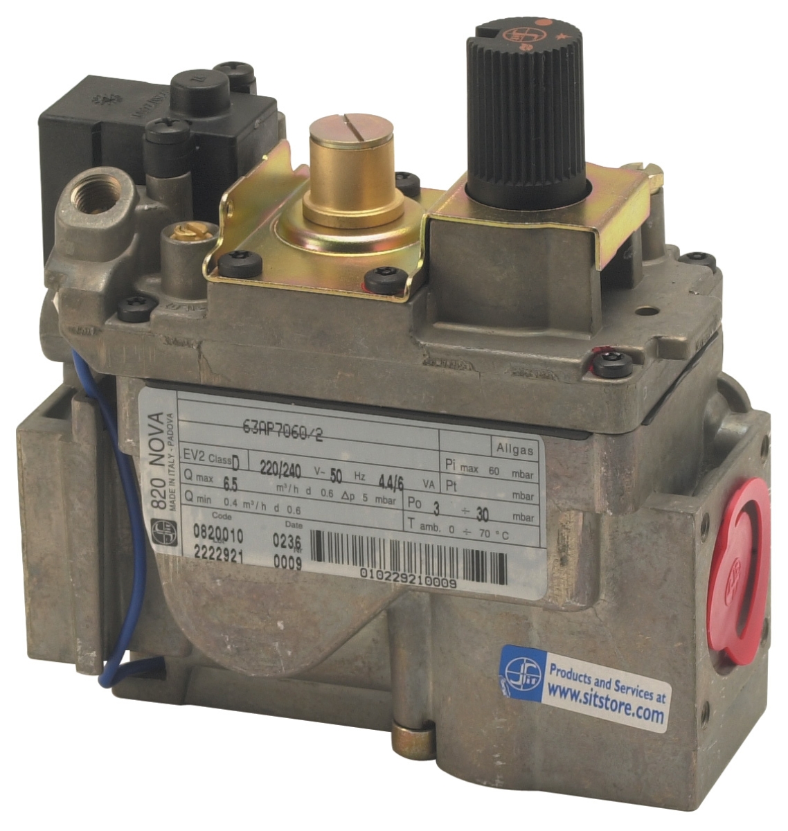
Electrical faults also cause lockout events. The Honeywell VK 4105 C 1041 U gas block and Sit Tandem gas block 0830042 depend on clean electrical signals from the relay to open solenoid valves. If the relay detects voltage anomalies on its outputs—indicating a shorted valve coil or damaged wiring—it will lock out rather than risk creating a safety hazard. Many relays test their output circuits during the startup sequence; if a short is detected, lockout occurs before ignition is even attempted.
Step-by-Step Diagnostic Procedure for Lockout Troubleshooting
Step 1: Safety and Documentation Before beginning diagnosis, ensure the burner is isolated from fuel and electrical supply. Document the exact sequence of events: when the lockout occurred, what was the system doing (ignition, steady-state firing, or shutdown), and what LED indicators are displayed. Check the maintenance log for recent work or component changes.
Step 2: Visual Inspection of Combustion System Physically inspect the burner head and combustion chamber for evidence of abnormal operation. Look for soot accumulation (indicating incomplete combustion), fuel leaks around solenoid connections, or damaged ignition electrodes. If the Sit Pilot light with 2 flames is used, visually confirm pilot light positioning and check that the thermocouple is correctly seated.
Step 3: Flame Sensor Cleaning and Reseating Flame sensors are the most common source of nuisance lockouts. If your system uses a UV or infrared detector like the Satronic Base for TF 9 poles, carefully remove it and inspect the lens for soot or dust. Use lens-cleaning solution and a soft cloth; do not use solvents that damage optical coatings. Reseat all flame sensor connectors firmly. For ionization-based detection, ensure the electrode gap is correct (typically 2.5–4 mm) and free of deposits.
Step 4: Pressure Switch Function Testing Using a calibrated pressure gauge, confirm that air and gas pressures at the burner are within design specifications. Manually operate pressure switches to verify they click cleanly at their set points. If a Honeywell C 6097 A 4110 or Kromschroder DG 50U/6 is suspected, disconnect it safely and jumper its contacts; if the relay no longer locks out during ignition, the pressure switch itself is faulty.
Step 5: Solenoid Valve Continuity and Coil Testing Measure electrical continuity across solenoid coils using a multimeter. A typical gas solenoid presents 20–100 ohms resistance depending on voltage rating and coil design. If a coil reads open (infinite resistance) or very low resistance (shorted), the valve must be replaced. Test the relay's output voltage to the solenoid under controlled conditions (fuel supply isolated) to ensure the relay is delivering the correct voltage.
Step 6: Relay Manual Reset and Controlled Restart Once potential faults have been addressed, perform a controlled manual reset of the relay according to the manufacturer's procedure—typically involving a reset button or momentary disconnect of the control power. Document whether the system restarts normally or immediately re-locks, as this behavior guides further investigation.
Selection and Replacement Guidance for Fault-Prone Scenarios
When diagnostic procedures identify a faulty relay component, replacement strategy depends on the appliance type and operational duty cycle. For atmospheric burners in intermittent operation, the Brahma Relay CM 11F TW1.5/TS10 from the MICROFLA T Series is a proven choice for combi boilers, heating boilers, and warm-air generators rated up to typical residential/light commercial power levels. Its solid ignition device and built-in EMI filter reduce susceptibility to electrical noise—a common cause of nuisance lockouts in industrial environments.
For larger fan-assisted burners, the Brahma CM 31 provides higher reliability in demanding applications. Both models feature two independent safety contacts in series on the gas valve output, ensuring that a single contact failure cannot bypass safety logic.
When selecting replacement sensors and switches, ensure compatibility with your relay model. The Danfoss RT 5 pressure switch family offers multiple setpoint ranges (RT 110: 0.2–3 bar, RT 112: 0.1–1.1 bar, RT 113: 0–0.3 bar, RT 116: 1–10 bar, RT 117: 10–30 bar); confirm the installed range before ordering replacements.
For multifunctional control applications where pressure regulation, flame supervision, and temperature control are combined in a single device, the Sit 710 MINISIT gas control block offers thermoelectric flame supervision with pressure regulation suitable for stoves, boilers, and catering equipment, meeting EN 126 standards with 5000 expected cycle life.
Document all replacements with part numbers, installation date, and function test results. Maintain a historical log of lockout events; repeated lockouts on the same component after replacement may indicate a different root cause (such as system pressure instability or electrical interference) rather than component failure.
Preventive Maintenance and Best Practices to Reduce Lockout Frequency
Reducing nuisance lockouts extends equipment life and improves system reliability. Establish a preventive maintenance schedule that includes quarterly flame sensor cleaning, annual pressure switch calibration, and inspection of all electrical connections for corrosion or looseness. Ensure proper grounding of all control wiring to reduce electrical transient coupling—particularly important in industrial environments with high-power switching equipment nearby.
Verify that fuel quality meets specification, as contaminated fuel or incorrect grade can cause combustion instability and flame sensor confusion. For oil-fired systems, change fuel filters at intervals recommended by the equipment manufacturer; clean fuel reduces sensor fouling and solenoid valve stiction.
Consider upgrading to relay systems with advanced diagnostics and fault logging, such as those integrated with building management systems. The Honeywell TFI 812.05 for 2-speed gas burners combines ionization and infrared flame detection, providing redundant sensing that reduces nuisance lockouts from single-sensor failures. The dual-sensor approach offers greater immunity to transient flame perturbations.
Ensure that all personnel involved in maintenance understand the specific relay model and its reset procedure. Improper reset attempts—such as repeatedly cycling power—can mask the true fault and complicate later diagnosis. Train staff to document the relay's LED status, any audible signals, and the exact operational sequence when lockout occurs.
When to Contact Technical Support and Escalation Procedures
If systematic troubleshooting—including sensor cleaning, pressure verification, continuity testing, and relay reset—does not restore stable operation, or if lockouts recur within hours of a successful reset, the root cause likely involves either a complex electrical fault, a relay processor failure, or a systematic combustion control problem beyond field diagnosis. In these cases, consult the relay manufacturer's technical documentation or contact equipment service support.
Lockout events triggered immediately upon power application (before ignition is even attempted) indicate electrical faults that require professional testing equipment to isolate. Similarly, intermittent lockouts that occur randomly during steady-state operation may reflect environmental factors such as electrical noise, vibration-induced contact issues, or gradual component drift that require factory refurbishment or replacement.
3G Electric maintains a comprehensive inventory of replacement relays, sensors, and safety switches from leading manufacturers worldwide, supported by technical documentation and application expertise. If your troubleshooting procedures have narrowed the fault to a specific component, our team can help you identify the correct replacement and ensure proper installation and function testing.
Conclusion and Action Steps for Maintenance Teams
Burner control relay lockout failures are frustrating but manageable when approached systematically. The key to effective troubleshooting is understanding that non-volatile lockout is a feature, not a bug—it protects your equipment and personnel by refusing to operate until faults are corrected. By following structured diagnostic procedures, documenting all findings, and maintaining comprehensive maintenance records, your team can dramatically improve system uptime and reduce safety risks.
Start with the fundamentals: flame sensor cleanliness, pressure switch calibration, and electrical continuity testing. Progress logically through fuel supply, ignition function, and relay output verification. When standard procedures do not resolve the issue, escalate to manufacturer technical support or field service engineers with detailed documentation of your troubleshooting steps.
Contact 3G Electric today to discuss your specific control system challenges, request technical documentation for your relay model, or order replacement sensors and switches. Our team has served industrial equipment customers since 1990 and can help you build a reliable, long-lasting combustion control system. Explore our complete Controls & Safety product range, or review our flame detection sensor options and pressure switch solutions. We also offer detailed information on multifunctional gas control blocks for integrated system applications.