Gas Burner Maintenance & Service: Combustion System Diagnostics and Component Care for Industrial Applications
Industrial gas burners are critical infrastructure in manufacturing facilities, heating systems, and process applications worldwide. Unlike static equipment, burners operate under high thermal stress with continuous combustion cycles that demand rigorous maintenance protocols. This guide addresses a maintenance angle distinct from valve control systems—focusing on the combustion chamber itself, flame quality assessment, fuel delivery optimization, and the supporting piping infrastructure that ensures reliable burner performance. For procurement engineers managing multi-unit facilities or single-burner installations, understanding combustion diagnostics and preventive maintenance extends equipment life, reduces unplanned downtime, and ensures operational safety across diverse industrial environments from Southeast Asia to global markets.
Understanding Combustion System Maintenance Requirements
Gas burner maintenance centers on three interconnected systems: the combustion head assembly, the fuel delivery mechanism, and the ignition/monitoring infrastructure. Unlike oil-fired systems that require frequent nozzle cleaning and tank management, gas burners present distinct challenges rooted in fuel purity, air mixing efficiency, and flame stability under varying load conditions.
The combustion head assembly—where fuel and air meet and ignite—is the primary wear zone. Over time, burner ports can accumulate carbon deposits, scale, or debris that distort the flame pattern and reduce combustion efficiency. This degradation occurs gradually, making routine visual inspection essential. A healthy gas flame should exhibit a stable, blue-tinged combustion zone without yellow or orange regions, which indicate incomplete combustion and carbon formation.
The fuel delivery circuit—from the main gas supply through the burner body and into the combustion chamber—must maintain precise pressure regulation and flow consistency. Pressure fluctuations, even within 5-10%, can cause flame lift-off, flame impingement on burner walls, or incomplete fuel atomization. This is where pressure monitoring becomes critical; facilities operating multiple burners or high-capacity single units must establish baseline pressure readings during commissioning and track deviations over time.
The third system involves the ignition and flame monitoring infrastructure. Modern burners often include electrodes for spark ignition and flame sensors (typically flame rod or UV-based) that verify combustion before the fuel valve fully opens. Fouled or misaligned ignition electrodes prevent reliable startup, while degraded flame sensors create unnecessary shutdowns or fail-safe scenarios that halt operations.
Seasonal variations—particularly in tropical climates like Singapore where high humidity and salt-laden air accelerate corrosion—intensify these maintenance demands. Routine inspection intervals should reflect local environmental conditions and operational duty cycles.
Technical Diagnostics and Supporting Equipment for Burner Assessment
Effective gas burner maintenance requires hands-on diagnostic capability. Three equipment categories form the foundation of a maintenance toolkit for burner professionals.
Pressure Monitoring and Measurement: Accurate fuel pressure assessment is non-negotiable. The CBM Glycerin Stainless Steel Pressure Gauge (Vertical, 0-4 bar, G1/4 connection) provides direct, real-time fuel pressure visibility at the burner inlet. The glycerin-filled design dampens pressure pulsations common in gas fuel trains, providing stable needle movement that simplifies reading accuracy even during transient flow conditions. For facilities in corrosive environments, the stainless steel wetted parts resist salt-air degradation. Mount this gauge on the gas supply line upstream of the main fuel valve to establish baseline pressure and detect deviation patterns that signal regulator drift or supply-side obstruction.
Piping Integrity and Flow Configuration: The fuel delivery path must be optimized for smooth flow and minimal turbulence. The CBM Flat Elbow 90° (60mm) provides low-resistance directional change in gas supply lines. Unlike standard elbows that create swirl and pressure drop, flat elbows maintain laminar flow characteristics, reducing erosion and pressure loss. This becomes critical in systems operating near the burner's minimum pressure threshold (typically 25-35 mbar for natural gas in modulating burners like the FBR X5 series). Improper piping geometry can introduce 10-15 mbar unnecessary loss, potentially limiting burner turndown ratio or causing unstable flame behavior at low-fire operation.
Electrical and Temperature Diagnostics: The CBM Automatic Multimeter MM420 enables verification of ignition electrode voltage (typically 8-12 kV for spark ignition), flame rod sensing current, and solenoid coil resistance. Low solenoid resistance readings (target: 35-50 ohms for 120V coils) indicate coil integrity; resistance exceeding 100 ohms signals moisture ingress or winding degradation. For infrared temperature assessment of combustion chamber condition, the CBM Type K Thermocouple delivers localized heat measurement, enabling technicians to verify uniform heat distribution across the combustion zone—non-uniform readings suggest blocked ports or flame impingement.
The CBM Non-Contact Voltage Detector provides safe electrical troubleshooting without direct probe contact, reducing arc risk near sensitive burner electronics in high-voltage ignition circuits.
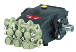
Fuel Delivery System Pumps: Facilities operating atmospheric gas supply lines typically do not require external pumping; however, operations in low-pressure zones, applications requiring fuel pressure boosting, or dual-fuel installations may integrate small modulating pumps. The Interpump E3B2515I series pumps (7.13 kW, 15 L/min at 250 bar) serve auxiliary fuel circulation roles in complex heating systems, maintaining consistent delivery pressure to multiple burner units or supporting fuel conditioning circuits. While not primary burner components, these pumps prevent supply-side pressure collapse during high-demand startup phases.
Real-World Application: Multi-Burner Facility Maintenance in Tropical Operations
Consider a mid-size industrial facility in Southeast Asia operating three natural gas burners (each rated 150 kW nominal output) for process heating. The facility maintains a hot water loop serving multiple production departments.
Initial Commissioning and Baseline Documentation: Upon equipment installation, technicians establish baseline measurements: fuel supply pressure at each burner inlet (target: 30-32 mbar for natural gas operation), ignition voltage confirmation, flame sensor current draw during stable combustion (4-6 mA typical), and combustion head surface temperature at three points (center, mid-radius, edge). These readings are documented in the facility's maintenance log.
Monthly Visual Inspection Protocol: Technicians observe flame color and stability during startup, full-fire operation, and shutdown transients. Any yellow flame edges, black soot visible on the combustion head, or delayed ignition (>2 second spark duration before flame establishment) triggers diagnostic intervention.
Quarterly Pressure Trend Analysis: Using the CBM pressure gauge mounted at each burner, technicians record inlet pressure readings during 100% load operation. A 3-5 mbar drift from baseline over one quarter suggests regulator creep or upstream obstruction. Pressure readings below the minimum threshold require gas supply line inspection and cleaning (sediment accumulation is common in older infrastructure or after major supply network maintenance).
Six-Month Deep Diagnostic: Remove the combustion head assembly and visually inspect for carbon deposits, scale buildup, or mechanical damage. Use the multimeter to verify solenoid coil resistance and ignition electrode continuity. If resistance readings deviate >20% from baseline or thermocouple readings show >15% non-uniformity across the combustion zone, schedule combustion head service or replacement.
Tropical Environment Specific Actions: In high-humidity, salt-air zones, stainless steel components require semi-annual cleaning with fresh water rinse and light lubrication of mechanical linkages. The glycerin-filled pressure gauge resists moisture ingress better than dry gauges; quarterly inspection of the gauge glass for condensation or discoloration indicates seal degradation requiring replacement.
Selection Criteria and Best Practices for Burner Maintenance Programs
Establish Equipment-Specific Baselines: Every burner model exhibits unique pressure requirements, ignition voltage specifications, and flame sensor current profiles. Consult the burner manufacturer's technical documentation (e.g., the FBR X5/MF series specification sheet) to establish facility-specific normal ranges. Deviations exceeding ±10% warrant investigation.
Invest in Redundant Measurement Capability: Maintain two pressure gauges—one installed on the active system for real-time monitoring, one spare calibrated and tested annually. A portable gauge enables quick cross-verification if the installed gauge becomes suspect.
Document All Interventions: Create a maintenance record for each burner unit: dates of inspection, measurements taken, components cleaned or replaced, and flame quality observations. This historical record identifies recurring issues (e.g., frequent pressure regulator drift) that justify component upgrade or supply-side infrastructure investment.
Train Maintenance Staff on Electrical Safety: Gas burner diagnostics involve high-voltage ignition circuits and live fuel supply lines. Ensure technicians understand proper lockout/tagout procedures, safe use of the non-contact voltage detector, and secure grounding techniques before work begins.
Align Maintenance Intervals with Operational Load Profile: Burners operating continuous high-fire duty require more frequent inspection than intermittent or modulating units. Facilities with variable process loads benefit from enhanced pressure and flame monitoring during startup and shutdown transients, where thermal cycling and flow disturbances create peak stress conditions.
Supporting Infrastructure and System Optimization
Beyond the burner combustion zone, the fuel supply infrastructure demands equal attention. Clean, dry gas free of particulate matter and liquid water ensures stable burner operation. For facilities managing multiple service circuits, the CBM Wall Bracket (400mm capacity, 100 kg load support) provides secure, organized mounting for pressure gauges, control modules, and measurement instruments within arm's reach of maintenance technicians. Proper equipment positioning reduces troubleshooting time and improves safety by keeping diagnostic tools readily accessible during active system assessment.
Gas supply line piping quality directly impacts burner performance. Low-pressure gas systems (under 50 mbar) are sensitive to friction losses; undersized piping or excessive fittings can introduce 15-20 mbar total loss, potentially preventing proper burner modulation or flame stability. The flat elbow design minimizes such losses compared to standard elbows.
Conclusion: Proactive Burner Maintenance as Operational Insurance
Gas burner maintenance extends far beyond annual service calls. A robust diagnostic program using appropriate instrumentation—pressure gauges, multimeters, thermocouples, and voltage detectors—empowers maintenance teams to detect degradation early, before it manifests as safety shutdowns or efficiency loss. In tropical environments where environmental stressors accelerate component aging, quarterly pressure assessments and semi-annual deep diagnostics provide measurable ROI through extended equipment life and reduced unplanned downtime.
3G Electric supplies comprehensive diagnostic equipment, piping components, and supporting infrastructure to enable this proactive approach across global industrial operations. Contact 3G Electric today to discuss your facility's specific burner maintenance requirements, obtain calibrated pressure gauges suited to your operating environment, and access technical guidance for establishing a maintenance protocol aligned with your equipment specifications and operational demands.