How to Select and Configure Gas Valves & Regulators for Industrial Burner Systems: A Technical Procurement Guide
Selecting the right gas valves and regulators for industrial burner systems requires a systematic approach combining pressure ratings, flow capacity analysis, safety compliance, and application-specific requirements. This comprehensive guide walks procurement engineers through the decision-making process, from initial system assessment to final component configuration. Improper valve selection can result in system inefficiency, safety hazards, and costly downtime. Understanding pressure drop calculations, switching frequency requirements, and safety interlock specifications is essential for optimal combustion system performance and regulatory compliance across global industrial applications.
Understanding Gas Valve and Regulator Fundamentals for Burner Systems
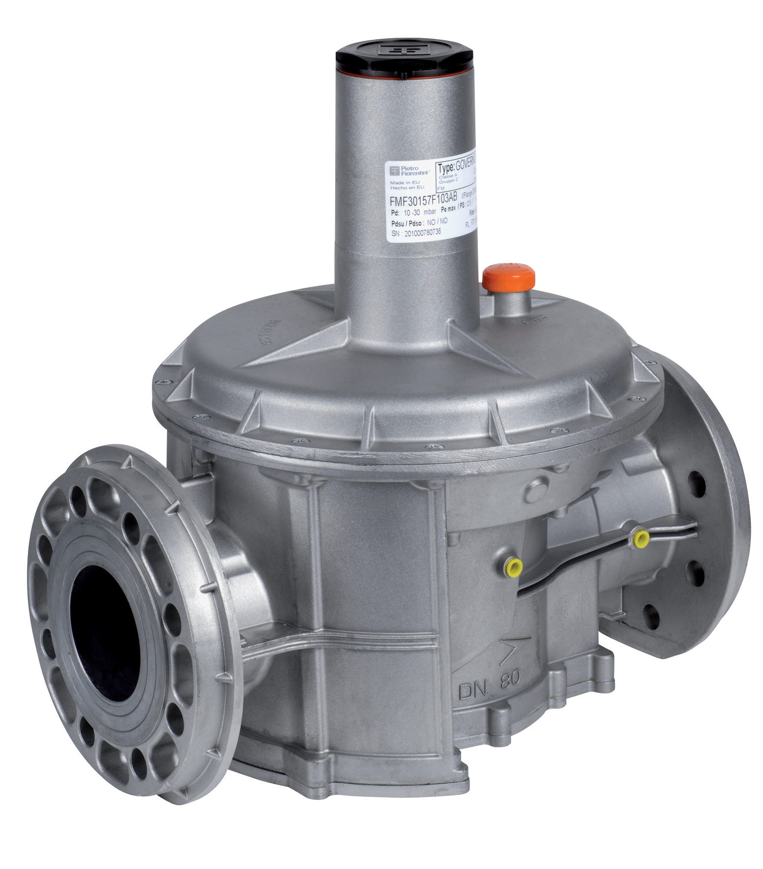
Gas valves and regulators serve distinct but complementary functions in industrial burner systems. Regulators control and maintain consistent outlet pressure within specified ranges, while solenoid valves provide on-off control and safety shutdown capability. The selection process begins with understanding these core functions and how they interact within your combustion system architecture.
Pressure regulators work by sensing downstream pressure through a pilot line and mechanically or electronically adjusting inlet flow to maintain setpoint pressure. Self-acting regulators like the Francel B25/37mb use a balanced diaphragm design to achieve this without external power, making them reliable for applications where electrical supply is unreliable or unavailable. These regulators deliver fixed outlet pressure—in this case 37 mbar—with integrated safety relief to prevent overpressurization.
Gas safety valves, conversely, must respond rapidly to system faults. The Dungs MVD 515/5 exemplifies modern safety valve design, opening in less than 1 second when energized and incorporating a 1 mm integrated filter mesh to protect downstream equipment from particulate contamination. This sub-second response time is critical for burner flame-out conditions where fuel must be cut off immediately to prevent dangerous accumulation.
Temperature range compatibility is often overlooked during selection but critically affects valve sealing integrity and solenoid coil longevity. The Dungs MVD 515/5 operates across −15 °C to +60 °C, making it suitable for both outdoor industrial sites and temperature-controlled mechanical rooms. For applications exposing valves to higher ambient temperatures, thermal management through installation location and shielding becomes necessary. System pressure rating determines component maximum safe working pressure; the 200 bar rating of the Dungs MVD 515/5 provides significant safety margin for typical gas burner applications operating at 20–100 mbar.
Technical Specifications and Pressure-Flow Selection Criteria
The selection process must account for three interdependent variables: maximum system pressure, minimum pressure drop requirements, and maximum flow demand. Begin by mapping your burner's fuel consumption across all operating stages. For a two-stage burner like the FBR GAS XP 60/2 CE TC EVO, which delivers 116–630 kW thermal power, fuel consumption ranges from 11.6 m³/h at minimum fire to 63.3 m³/h at full load. This wide turndown ratio necessitates valves capable of precise modulation across the entire operating envelope.
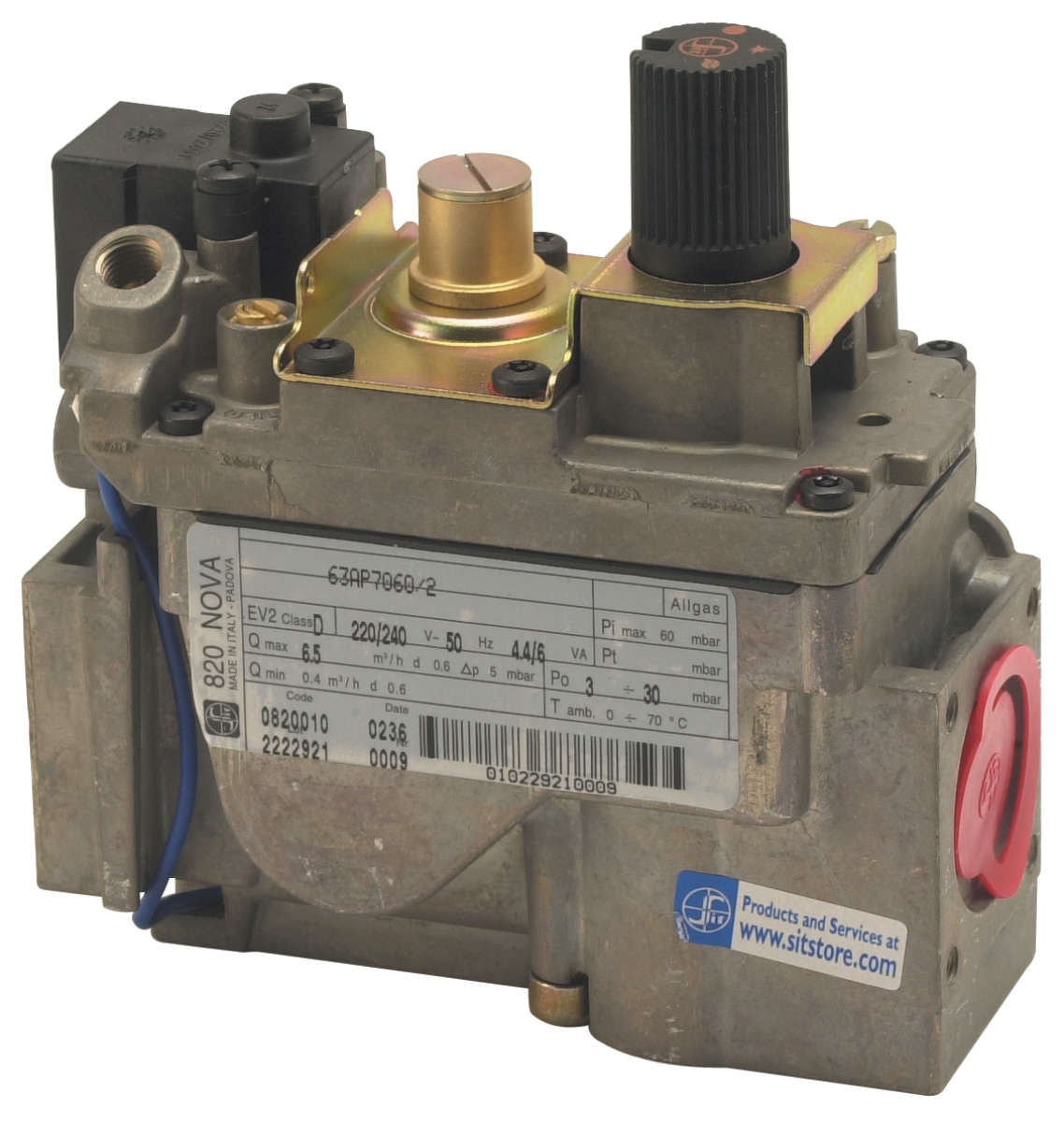
Pressure drop across gas safety valves directly impacts burner control range and flame stability. Most industrial applications tolerate maximum 5–10 mbar pressure drop to preserve adequate downstream pressure headroom. The Sit tandem gas block demonstrates low-loss design, creating only 5 mbar differential while delivering 4.8 m³/h for family II gases and 6.2 kg/h for family III gases. This minimal pressure loss maintains precise pressure regulation across modulation range, critical for burners requiring stable combustion across partial-load conditions.
For pressure regulation in laboratory and low-pressure distribution systems, the Francel B25/37mb with its 37 mbar outlet setpoint and 10 mm vent size provides economical pressure control in applications such as analytical gas supply, small research burners, or municipal gas distribution pilot systems. The flat meter outlet joint provides standardized connection compatibility across instrument manufacturers.
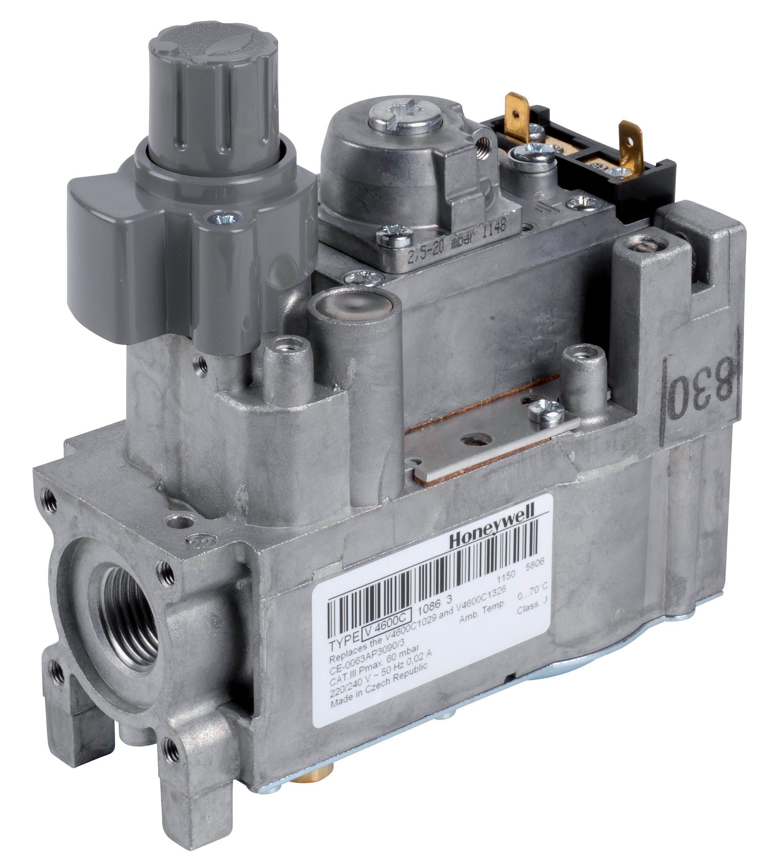
Solenoid response characteristics become significant when considering switching frequency. The Dungs MVD 515/5 supports up to 20 cycles per hour—sufficient for most burner on-off cycling but inadequate for modulating burner systems requiring proportional valve banks or mass flow controllers. For modulating applications, electric pressure regulators like the Honeywell VK 4105 C 1041 U with M8 × 1 pilot connection and M5 pressure feedback threading enable continuous proportional control over wide operating ranges.
Connection sizing must match both inlet and outlet piping dimensions to minimize velocity-induced pressure drop and noise. Standard industrial connections range from G1/2" through G2", with larger diameter suitable for high-flow applications. Material compatibility—stainless steel for corrosive environments, cast iron or aluminum for standard indoor applications—extends component lifespan and prevents unexpected failures.
Step-by-Step Configuration Guide for Burner Gas Systems
Step 1: Determine System Pressure Requirements
Document your gas supply pressure at the inlet (typically 200–250 mbar for natural gas distribution, 50–100 mbar from on-site LPG storage). Measure pressure drop across existing piping, valves, and filters to calculate available pressure at the burner regulator inlet. This available pressure minus your target outlet pressure determines maximum allowable pressure loss across all components.
Step 2: Calculate Peak and Minimum Flow Demand
Obtain burner fuel consumption specifications from the manufacturer's commissioning documentation. For the FBR GAS XP 60/2 CE TC EVO, confirm whether the specified 11.6/23.3–63.3 m³/h represents natural gas (lower heating value ~10 kWh/m³) or LPG (higher heating value ~12.8 kWh/kg). Apply a 15–20% safety margin above peak consumption when selecting valve flow ratings.
Step 3: Select Primary Pressure Regulator
Choose between self-acting regulators (no power required) and electric modulating regulators (proportional control capability). Self-acting units like the Francel B25/37mb suit simple on-off burner applications, while modulating burners require electric regulators providing continuous pressure adjustment signals.
Step 4: Specify Safety Valve Solenoid Coil and Electrical Interlocks
Select solenoid voltage matching your facility electrical standard (230V AC, 24V DC, or 120V AC). The Elektrogas Coil 1930.3120 230V EVRMNCA exemplifies rated solenoid specifications (25 W at 230V) for typical European industrial installations. Configure electrical interlocks to de-energize solenoids during flame-out conditions, pilot pressure loss, or emergency shutdown.
Step 5: Install Pilot Line Connections and Safety Devices
Route pilot pressure lines (typically 1/4" or 3/16" tubing) from main outlet to regulator pilot inlet with minimum bends and maximum diameter to reduce response lag. Install a 100 µm pilot filter upstream of regulator pilot inlet to protect the balance diaphragm from contamination. The Elektrogas VMM 20-25 with 3 mm Allen wrench adjustment demonstrates how valve tuning requires accessible mechanical adjustments.
Step 6: Pressure Test and Commission the System
Pressurize the system slowly to 1.5× maximum working pressure using nitrogen (never oxygen). Monitor all connections for leakage. Verify outlet pressure under no-flow conditions (regulator static pressure) and at maximum flow demand (regulator dynamic pressure). Record all setpoint values in the maintenance documentation.
Selection Criteria and Best Practice Comparison
| Selection Criterion | Self-Acting Regulators | Electric Modulating Regulators | Safety Solenoid Valves |
|---|---|---|---|
| Control Precision | ±5% setpoint hold | ±1% setpoint hold | On-off binary control |
| Power Requirement | None (passive) | 24V DC or 120/230V AC | 24V DC or 120/230V AC solenoid |
| Response Time | 2–5 seconds to setpoint | 500 ms proportional adjustment | <1 second shutdown (safety critical) |
| Minimum Pressure Drop | 3–10 mbar | 2–5 mbar (pilot line design) | 5–15 mbar depending on flow |
| Typical Applications | Fixed-load burners, pilot supplies | Modulating burners, load-following | All burners (mandatory safety component) |
| Maintenance Interval | 24–36 months (diaphragm inspection) | 12–18 months (solenoid coil check) | 6–12 months (coil and valve seat) |
When comparing specific products for your application, evaluate pressure setpoint repeatability after thermal cycling. The Francel B25/37mb with integrated safety relief provides both primary regulation and overpressure protection in a single compact unit, reducing component count and connection points. However, the electric modulating capability of the Honeywell VK 4105 C 1041 U becomes essential in applications with varying load demand where maintaining constant burner outlet pressure across modulation swings optimizes flame stability.
For installations in demanding environments—such as outdoor industrial sites, food processing facilities with moisture ingress, or plants subject to vibration from neighboring equipment—specify stainless steel body construction and pilot line materials resistant to corrosion. Solenoid coil protection rating (IP40 minimum for industrial duty) determines coil lifespan in spray and washdown environments.
Documentation and labeling of all setpoints, serial numbers, and calibration dates on pressure regulators ensures compliance with periodic inspection requirements. Many jurisdictions mandate annual certification of regulator setpoint accuracy by qualified technicians, making procurement from suppliers providing traceable calibration certificates essential for regulatory compliance.
Real-World Integration with Industrial Burner Systems
Consider a typical installation: a small industrial facility requiring heat for steam generation using a two-stage modulating burner (like the FBR GAS XP 60/2 CE TC EVO) fed by bottled LPG. The selection process begins with supply pressure documentation (typically 4–6 bar from cylinder regulator) and burner fuel demand across both fire stages. With a 250 mm nozzle and 110 W fan motor, this burner requires stable pressure supply to maintain flame geometry across 116–630 kW modulation range.
The primary pressure regulator (self-acting Francel type for fixed setpoint or electric modulating Honeywell type for load-following) reduces cylinder pressure to burner inlet setpoint, typically 100–150 mbar. A solenoid safety valve like the Dungs MVD 515/5 sits downstream of the main regulator, energized during burner operation and de-energized during shutdown or flame-out, preventing unburned fuel accumulation. Pilot pressure is derived from the main outlet through a small solenoid-operated pilot isolation valve, ensuring pilot supply only when the burner is commanded on.
For facilities operating multiple burners on a common gas supply line, cascade regulator design minimizes pressure interaction: a main line regulator maintains supply pressure to a distribution header, while individual burner regulators maintain isolated outlet pressures for each burner. This isolation prevents one burner's modulation from affecting neighboring burner outlet pressure, critical for equal load sharing across parallel boiler trains.
Closure and Next Steps
Selecting and configuring gas valves and regulators requires balancing pressure ratings, flow capacity, response characteristics, safety compliance, and environmental durability. This guide provides the technical framework for making those decisions systematically, with reference to proven industrial components like the Francel B25/37mb, Dungs MVD 515/5, FBR GAS XP 60/2 CE TC EVO, and Honeywell VK 4105 C 1041 U.
Every installation presents unique pressure, flow, and environmental challenges. Contact 3G Electric's technical team to review your burner system specifications, pressure calculations, and regulatory requirements. Our procurement specialists work with leading manufacturers globally to source components matching your exact application needs, providing technical documentation, pressure testing certificates, and post-sale commissioning support. Explore our complete gas valve and regulator product range, and reach out to discuss your next industrial burner system project.