Understanding Real-Time Operational Monitoring for Pumps & Compressors
Effective management of Pumps & Compressors in Singapore's demanding industrial environment requires moving beyond reactive maintenance toward predictive operational monitoring. With over 35 years of distributing industrial equipment, 3G Electric has observed that plants implementing real-time diagnostics reduce unexpected downtime by 40-60% compared to schedule-based maintenance alone.
Real-time monitoring means continuously observing key performance indicators (KPIs) during normal operation, creating a baseline for your equipment, and recognizing deviations before they become catastrophic failures. For Pumps & Compressors, this includes tracking discharge pressure, inlet pressure, flow rate, motor current draw, fluid temperature, and bearing vibration simultaneously. The challenge is translating raw sensor data into actionable intelligence that guides maintenance decisions.
Unlike traditional troubleshooting that addresses problems after they manifest, real-time diagnostics allows plant managers to schedule maintenance during planned downtime windows, source replacement components in advance, and allocate technician resources strategically. This approach is particularly critical for Singapore operations where equipment uptime directly impacts manufacturing schedules and supply chain commitments.
Establishing Performance Baselines and Detecting Anomalies
The foundation of effective Pumps & Compressors diagnostics is establishing and documenting baseline operational parameters when equipment is new or recently serviced. Baselines become your reference point—any significant deviation signals a potential issue developing within the system.
Critical baseline parameters to document:
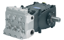
- Discharge pressure at full load: For example, the Pratissoli KF30 industrial pump operates at a baseline of 200 bar. Record the exact pressure your installation achieves during normal operation, not just the rated maximum.
- Inlet pressure (suction side): Should remain near atmospheric or slightly negative, typically -0.3 to 0 bar. Rising inlet pressure suggests suction-side restrictions.
- Motor current draw: Document amp consumption at 100%, 75%, and 50% load conditions. Deviations of ±15% from baseline warrant investigation.
- Fluid temperature stabilization point: Most systems reach steady-state thermal conditions within 30-45 minutes of operation. Record the temperature at which your pump stabilizes under standard load.
- Vibration signature: Modern vibration sensors produce frequency data that reveals bearing degradation, impeller wear, or cavitation long before audible symptoms appear.
Establishing these baselines requires taking measurements during the first 500 operating hours of equipment installation, under representative load conditions. Use standardized data collection sheets or integrate readings into your CMMS (Computerized Maintenance Management System) for automatic anomaly detection.
Interpreting deviation patterns:
When discharge pressure gradually increases 10-15 bar above baseline while flow rate remains constant, internal leakage is likely developing—worn pump internals allow fluid to bypass without contributing to output flow. This pattern indicates the pump is nearing replacement, typically 3-6 months from failure depending on severity.
If discharge pressure drops suddenly by 20+ bar while inlet pressure remains normal, check for worn impellers, cavitation, or a developing mechanical seal leak. The Pratissoli MW40 pump, rated for 210 bar, will show measurable pressure decline when internal components wear beyond specification tolerances.
When motor current increases 20-25% above baseline while pressure and flow remain constant, expect rising internal friction—bearings may be degrading, or fluid viscosity has changed due to contamination or thermal breakdown. This is an early warning sign warranting immediate fluid analysis and bearing inspection.
Sensor Selection and Data Integration Strategies
Effective real-time diagnostics requires appropriate sensor technology matched to your Pumps & Compressors specifications and facility infrastructure. Plant managers must understand sensor limitations and appropriate placement to avoid false diagnostics.
Pressure sensors: Install calibrated digital pressure gauges (0.5% accuracy minimum) at pump discharge and inlet. For systems running below 100 bar, mechanical gauges suffice; above 150 bar, electronic sensors with data logging capability provide more precise trending. Position discharge sensors 300-500mm downstream of the pump outlet to capture stable readings after initial flow turbulence dissipates. Inlet sensors should mount directly on the suction line, no more than 1 meter from the pump inlet.
Flow measurement: Turbine flow meters (5-300 L/min range) or electromagnetic flow meters (for conductive fluids) provide continuous flow data. Electronic gear pumps like the Interpump E1D1808 L compact gear pump operating at 8 L/min can be monitored with low-range turbine sensors for precise output verification. Install flow meters in a vertical section of discharge piping where air pockets won't accumulate.
Temperature sensors: Platinum Resistance Temperature Detectors (RTD Pt100) offer ±0.5°C accuracy in tank-mounted or immersion configurations. Place them in the pump discharge reservoir, not at the pump outlet, where localized heating distorts readings. Many plants monitor two locations—one at the pump return line and one in the bulk reservoir—to detect localized overheating.
Vibration monitoring: Single-axis accelerometers detect linear vibration; triaxial sensors capture complex vibration patterns revealing bearing faults, impeller imbalance, or cavitation. For industrial Pumps & Compressors, permanent mounting of accelerometers using epoxy adhesive on the pump housing (never on flexible mounting feet) provides consistent baseline reference data. Modern vibration systems analyze frequency signatures automatically, comparing real-time data against historical baselines and alert plant managers when severity reaches thresholds requiring maintenance.
Data integration architecture: Connect all sensors to a central data logger or PLC that records readings every 60 seconds during operation. Store data in cloud-accessible platforms enabling plant managers to review trends remotely. This is essential for Singapore operations with multiple facilities or night-shift operations—critical data remains accessible without requiring on-site presence.
Actionable Diagnostic Decision Trees
Plant managers need practical decision protocols that translate sensor readings into specific maintenance actions. The following decision trees address the most common Pumps & Compressors diagnostic scenarios observed across industrial operations.
Scenario 1: Discharge pressure rising gradually
1. Verify pump speed hasn't increased (check motor RPM or VFD settings)—speed increases linearly affect pressure.
2. Inspect inlet pressure simultaneously—if also rising 3+ bar above baseline, check suction strainer for blockage; clean or replace strainer element.
3. If inlet pressure normal but discharge pressure elevated, perform fluid sample analysis for viscosity and contamination; contaminated fluid increases internal friction significantly.
4. If fluid analysis normal, inspect mechanical seal for micro-leakage (visible weeping around shaft seal housing); seals failing internally increase internal pump friction before external leakage appears.
5. If mechanical seal appears dry and fluid is clean, the pump is experiencing internal wear—schedule replacement within 30 days.
Scenario 2: Flow rate declining while pressure stable
1. Verify outlet line isn't restricted—close discharge gate valve partially to observe if pressure rises (indicates restriction) or remains stable (indicates pump wear).
2. Check suction strainer condition; blockage reduces inlet flow, causing flow output to decline without raising pressure—clean strainer immediately.
3. If inlet clear and outlet line open, measure motor current draw; if current decreased alongside flow, the pump is cavitating (not developing full displacement)—check fluid level, suction lift, and inlet line for air leaks.
4. If motor current unchanged and both inlet and outlet clear, the pump's internal displacement is reducing due to component wear—this pump requires replacement within 2 weeks.
5. For models like the Interpump ET1C1612 pump operating at 12 L/min, flow decline below 10 L/min at rated pressure indicates urgent maintenance need.
Scenario 3: Motor current elevated 20%+ above baseline
1. Check discharge pressure and compare to baseline; if pressure unchanged, internal friction has increased—inspect bearings for resistance and check fluid for contamination or viscosity change.
2. Measure fluid temperature; if elevated 15°C+ above normal operating point, the system is generating excess heat from internal friction or external restriction—inspect cooler operation and verify cooling water flow if applicable.
3. Perform bearing inspection: listen for audible noise (grinding or squealing), feel housing temperature manually (use infrared thermometer; localized hot spots indicate bearing friction), and observe vibration patterns.
4. If elevated current persists after bearing inspection shows normal conditions, extract and analyze fluid immediately for particle count, viscosity, and water content; contaminated fluid significantly increases motor loading.
5. If all inspections normal and fluid is clean, the motor itself may be failing (not the pump)—consult with motor service provider before replacing pump.
Scenario 4: Vibration amplitude increasing trend
1. Document vibration frequency content from accelerometer data; bearing wear typically produces vibration in 2-10 kHz range, while cavitation and impeller imbalance produce lower frequency (100-500 Hz) signatures.
2. For bearing-related vibration, inspect bearing endplay manually (if pump design allows access) or schedule bearing removal and inspection; bearing wear can progress rapidly once initiated.
3. For low-frequency vibration, check pump mounting bolts for looseness—tighten all fasteners to specification and retest vibration; loose mounting amplifies normal vibration by 3-5×.
4. If vibration persists after mounting tightening, inspect impeller (on axial piston designs like the Pratissoli SS71153 pump) for scoring or debris impact damage—impeller damage requires full pump replacement.
5. For moderate vibration increase without bearing wear or looseness detected, schedule planned maintenance within 4-6 weeks; do not operate indefinitely as vibration can damage seals and accelerate component wear.
Implementing Continuous Improvement in Diagnostic Practices
Successful real-time diagnostics requires establishing organizational routines for data review, interpretation, and action. Plant managers should schedule weekly reviews of sensor trends, monthly technical analysis meetings with maintenance teams, and quarterly strategy assessments to optimize diagnostic protocols.
Document all diagnostic findings in your CMMS or maintenance log, including sensor readings at the time of observation, visual inspection results, actions taken, and outcomes. This historical record reveals patterns—perhaps certain failure modes occur seasonally, or specific units fail more frequently, indicating design or application issues requiring corrective action.
With 35+ years of industrial equipment distribution experience, 3G Electric has supported plant managers across Singapore facing diverse Pumps & Compressors challenges. Our technical team can provide guidance on sensor selection, baseline establishment, and diagnostic interpretation tailored to your specific equipment and operational environment. Contact our Singapore support team to discuss implementing real-time diagnostics for your pumping systems.
Real-time monitoring transforms maintenance from reactive crisis management into strategic operational management, extending equipment life, improving reliability, and enabling plant managers to execute planned maintenance schedules that minimize disruption to production.