Industrial Pump Performance Degradation: Diagnosing and Resolving Pressure Loss Issues
Pressure loss in industrial pumps is one of the most common performance issues affecting manufacturing operations across Singapore. When your pumps and compressors fail to maintain rated pressure, production delays cascade throughout your facility, leading to costly downtime and reduced output. Whether you operate at 90 bar or 500 bar system pressures, understanding the root causes of pressure degradation is critical to maintaining operational efficiency. This troubleshooting guide equips industrial professionals with the diagnostic knowledge needed to quickly identify pressure loss issues, implement targeted solutions, and prevent recurrence—ultimately protecting your equipment investment and maintaining production schedules.
Understanding Pump Pressure Loss Mechanisms
Pressure loss in industrial pumps occurs through several distinct mechanisms, and understanding each is essential for accurate diagnosis. Internal leakage represents the primary culprit in most cases, where fluid bypasses the pump's delivery chamber through worn clearances between rotating and stationary components. As pump internals wear over time—typically measured in operating hours—clearance tolerances expand beyond design specifications, allowing pressurized fluid to escape back to the inlet or tank without performing useful work.
Cavitation damage, another critical failure mode, occurs when the inlet pressure falls below the vapor pressure of the hydraulic fluid, creating vapor bubbles that collapse violently when subjected to pressure. This implosion damages pump surfaces microscopically at first, but progressively deteriorates internal geometry, increasing clearances and accelerating pressure loss. Temperature elevation frequently accompanies cavitation, with fluid temperatures rising 5-15°C above normal operating range.
Valve blockage and contamination represent external pressure loss mechanisms. Particulate matter—iron fines, elastomer degradation products, or environmental contaminants—accumulates in relief valves and pressure-regulating components, preventing proper seating and causing creep (slow pressure bleed-off). Modern industrial facilities in Singapore often operate at high pressures where even microscopic contamination (particles larger than 10 microns) can compromise valve integrity. Additionally, air entrainment in the hydraulic fluid reduces bulk modulus, causing the system to "compress" rather than transmit pressure, resulting in apparent pressure loss at the gauge despite normal pump displacement.
Seal degradation follows predictable failure patterns. Elastomer seals deteriorate through thermal stress, chemical incompatibility with the hydraulic medium, or mechanical extrusion over years of operation. Once seals pass their service life, leakage paths open, and pressure cannot be maintained regardless of pump displacement or drive power. Understanding these mechanisms enables you to distinguish between temporary operational issues and permanent equipment degradation requiring replacement.
Technical Diagnosis: Identifying Root Causes in Real Systems
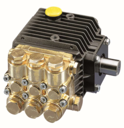
Systematic pressure testing reveals the specific failure mode affecting your system. Begin by measuring actual delivery pressure under full-load conditions and comparing against nameplate specifications. For example, the Interpump PUMP 5015 R ATEX maintains 500 bar (7250 psi) at rated conditions with 15 L/min flow. If your unit delivers only 450 bar under identical load, the 50-bar deficit indicates either internal leakage or external blockage.
Measure flow rate simultaneously with pressure measurement. The 5015 R ATEX should deliver precisely 15 L/min (3.96 US gpm) at 1450 rpm rotation regime. If flow remains constant while pressure drops, internal leakage dominates—worn clearances allow fluid bypass. Conversely, if both pressure and flow decrease proportionally, external system resistance has increased due to filter blockage or valve restriction.
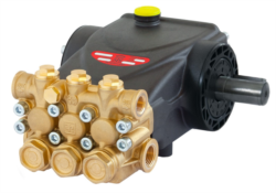
Temperature monitoring provides critical diagnostic data. Hydraulic fluid temperature should remain within 5°C of baseline under steady operation. Excessive temperature rise (above 65°C for mineral oil systems) indicates energy dissipation through leakage or friction. The Interpump PUMP E3E2815 R, rated at 275 bar and 15 L/min at 3400 rpm, generates approximately 70 kW of power. If 10% bleeds through leakage paths, 7 kW converts to heat, raising fluid temperature 3-4°C above normal.
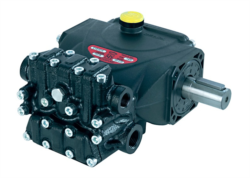
Visual inspection reveals external clues. Check for hydraulic fluid seepage around pump body, flange connections, and seal cartridges. The Interpump PUMP TT931 L, operating at 90 bar with 2.5 hp power input, should show no visible dripping. Minor weeping indicates incipient seal failure; active dripping confirms seal replacement is urgent. Inspect pump inlet lines for air bubbles—cavitation commonly produces visible foam in the reservoir. Listen for unusual noise: cavitation produces distinctive crackling sounds; worn bearings generate grinding or chirping noises.
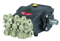
Pressure ripple analysis, possible with modern instrumentation, distinguishes pump displacement loss from external blockage. Pump pressure ripple (pulsation at shaft frequency) indicates volumetric output variation—the pump is reducing stroke or displacement. Steady-state pressure loss without ripple suggests external system restriction. The Interpump PUMP WW90 R operates at 2800 rpm, producing 37 pressure pulses per second (2800 ÷ 60 = 46.7 × number of pump chambers). Analyzing these ripples reveals whether the pump itself is damaged or system components are restricting flow.
Real-World Application Examples: Industrial Scenarios
Consider a Singapore manufacturing facility operating industrial equipment dependent on multiple pressure circuits. A facility using the Interpump 5015 R ATEX for high-pressure applications (500 bar, 20 hp power consumption) experienced sudden pressure loss during production—the pump maintained flow but pressure dropped from 500 bar to 420 bar over two weeks. Initial suspicion fell on internal wear, but systematic diagnosis revealed a partially blocked relief valve in the secondary circuit, caused by iron oxide contamination from a worn pump in a different system. After cleaning the relief valve, pressure restored to specification within 24 hours, costing the facility minimal downtime.
Another practical case involved a facility managing medium-pressure systems with the TT931 L pump (90 bar, 2.5 hp). Operators reported gradual pressure loss correlated with ambient temperature increase. Investigation revealed cavitation in the pump inlet line—suction strainers had become fouled, raising inlet restriction from 0.1 bar to 0.8 bar over several months. This reduced absolute inlet pressure below vapor pressure on warm days, initiating cavitation damage. Replacing strainer elements and increasing suction line diameter from 16mm to 20mm resolved the issue permanently, demonstrating how inlet design critically affects pump reliability.
A third scenario involved the WW90 R and WW90 L pump pair used in dual-circuit applications. One pump delivered specified pressure while the paired pump lost 15 bar. Visual inspection revealed hydraulic seepage at the flange connection to motor coupling. The B3/B14 flange mounting bolts had gradually loosened due to vibration over 18 months, opening microscopic gaps in the flange interface. Re-torquing bolts to specification restored seal integrity immediately. This highlights how maintenance of mechanical connections prevents cascade failures in industrial pump systems.
Selection and Maintenance Best Practices
Preventing pressure loss requires selecting appropriate equipment specifications and implementing rigorous maintenance protocols. Match pump selection to your duty cycle: continuous high-pressure applications demand robust designs like the 5015 R ATEX (500 bar rating), while intermittent medium-pressure uses suit the WW90 series (90 bar rating). Oversizing pumps creates unnecessary cost and energy consumption; undersizing causes accelerated wear and cavitation.
Establish preventive maintenance schedules based on manufacturer recommendations and actual operating hours. Monitor fluid condition quarterly—particle counting to ISO 16889 standards ensures contamination remains below 18/16/13 (the standard threshold for medium-pressure hydraulic systems). Change fluid completely every 3-5 years depending on operating temperature and environmental exposure. High-temperature operations (above 60°C continuous) reduce fluid life to 2-3 years.
For Singapore's tropical climate, thermal management deserves emphasis. Ambient temperatures consistently exceed 30°C, accelerating seal degradation and fluid oxidation. Install heat exchangers for systems operating above 55°C. Maintain suction lines properly: inlet filters should never exceed 0.5 bar pressure drop, and suction line velocity should not exceed 0.6 m/s to prevent cavitation. Replace high-pressure hoses every 5-7 years regardless of apparent condition—elastomer degradation occurs internally before external signs appear.
Document all pressure readings, temperatures, and maintenance actions in a maintenance log. Trend analysis reveals developing issues before catastrophic failure. If pressure declines more than 5% per month, immediate investigation is warranted. Use industrial pumps from reputable Singapore suppliers that provide comprehensive technical support and genuine replacement components—counterfeit parts cause premature failure and safety risks.
Closing and Expert Support
Pressure loss in industrial pumps demands systematic diagnosis rather than guesswork. By understanding internal leakage, cavitation, contamination, and seal degradation mechanisms, you can quickly identify root causes and implement targeted solutions. Whether your facility operates single-circuit systems or complex multi-pump installations, the diagnostic methodology outlined here applies universally.
3G Electric has served Singapore's industrial sector since 1990, providing expert guidance on pumps and compressors across all pressure ranges and applications. Our technical team understands Interpump equipment specifications intimately and can assist with diagnostics, component selection, and commissioning support. If your facility experiences persistent pressure loss or requires preventive maintenance planning, contact our Singapore office for a consultation. We'll help you restore optimal performance and maximize equipment lifespan—protecting your production schedule and operational budget.