Pressure Gauge Calibration & Monitoring Troubleshooting: Ensuring Accurate System Diagnostics in Industrial Applications
Accurate pressure monitoring is the foundation of reliable industrial system operation. When pressure gauges deliver inaccurate readings, maintenance teams face cascading problems: misdiagnosed equipment failures, inefficient system performance, and potential safety hazards. This troubleshooting guide provides maintenance engineers and service teams with systematic procedures to diagnose pressure gauge failures, verify calibration accuracy, and implement corrective measures across pumping systems, HVAC installations, and fluid delivery networks. Whether managing tropical climates in Singapore or operating in temperate industrial zones globally, understanding pressure gauge behavior and calibration protocols ensures data-driven decision-making and prevents costly downtime.
Understanding Pressure Gauge Measurement Accuracy & Common Failure Modes
Industrial pressure gauges operate within defined accuracy classifications—typically ±1.6% to ±4% of full-scale range depending on gauge type and manufacturing standard. When gauges deviate beyond these tolerances, root causes typically fall into three categories: mechanical degradation, environmental stress, or installation errors.
Mechanical degradation occurs when internal Bourdon tube elements (the curved metal sensing elements) lose elasticity through repeated pressure cycling or physical damage. Sustained high-temperature exposure, especially in tropical industrial environments like Singapore where ambient temperatures regularly exceed 30°C, accelerates material fatigue and internal corrosion of brass and copper components. Glycerin-filled gauge models provide improved resistance to vibration and pressure pulsation compared to dry gauges, making them preferred in high-shock applications.
Environmental contamination represents a major failure vector in humid coastal regions. Moisture ingress through worn gauge seals creates internal corrosion on the Bourdon tube and pointer mechanism, causing sticky needle response and zero-shift errors. Salt-laden air accelerates oxidation of ferrous components, even in epoxy-painted housings. This phenomenon is particularly pronounced in Singapore and Southeast Asian industrial zones within 10 kilometers of coastal areas.
Installation errors frequently go undetected during commissioning. Improper gauge orientation (installation outside the vertical mounting plane), inadequate snubbing or damping for pulsating pressure systems, and incompatible fluid connections generate persistent reading errors that maintenance teams incorrectly attribute to system malfunction rather than measurement apparatus failure.
Identifying whether a gauge is genuinely faulty or simply miscalibrated requires systematic diagnostic comparison against verified reference instruments and understanding pressure transient behavior specific to the connected system type.
Systematic Calibration Verification & Diagnostic Procedures
Accurate troubleshooting begins with reference instrument selection. The CBM Automatic Multimeter MM420 and CBM Non-contact Voltage Detector provide foundational electrical diagnostics for gauge circuits and signal integrity, while pressure calibration verification requires dedicated reference gauges or digital pressure transducers operating at certified accuracy levels (±0.5% or better).
Step 1: Visual Inspection and Environmental Assessment
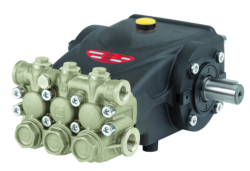
Begin by examining the gauge exterior for physical damage, moisture intrusion indicators, and proper orientation. Verify the gauge is mounted vertically (0° to 10° acceptable deviation per ISO 1817 standards). Check for accumulated dust or corrosive deposits on the case—common in tropical environments—and inspect all connection points for weeping or past leakage evidence. For systems using high-pressure applications like those served by Interpump PUMP E3B2515I R units operating at 250 bar (3,625 PSI), ensure the gauge range matches system operating parameters with a safety margin of 25-33% above maximum expected pressure.
Step 2: Static Pressure Comparison Testing
Isolate the suspect gauge from the live system using isolation ball valves. Connect both the test gauge and a certified reference pressure source to a common manifold. At zero pressure (atmospheric), both gauges should read 0 bar ±0.1 bar. At three calibrated test points (typically 25%, 50%, and 100% of full-scale range), record deviation magnitude. Deviations exceeding ±2% of full-scale range indicate calibration drift requiring professional recalibration or gauge replacement.
Step 3: Dynamic Response Assessment
For pulsating pressure systems—such as positive displacement pump discharge lines—oscillating gauge needles indicate system behavior, not gauge failure. However, sluggish needle movement or inability to settle within 2-3 seconds suggests internal restriction or damping fluid degradation. Glycerin-filled pressure gauges like the CBM Glycerin Stainless Steel Pressure Gauge, vertical D50 0/+4bar G1/4 incorporate viscous damping to suppress needle flutter while maintaining accurate pressure representation. If needle response is unexpectedly slow even in non-pulsating circuits, the gauge damping orifice may be obstructed—a condition requiring gauge replacement.
Step 4: Zero-Point Stability Over Time
Record gauge readings at atmospheric pressure at hourly intervals over an 8-hour period. Stable readings within ±0.2 bar indicate normal behavior. Progressive drift toward higher readings suggests internal spring relaxation; downward drift indicates leakage past the lower seal. Both conditions require recalibration or replacement. Sudden step-changes in zero reading often indicate pointer detachment from the internal spindle—a mechanical failure requiring gauge replacement.
Real-World Troubleshooting: Pressure System Integration & Diagnostic Scenarios
Scenario 1: High-Pressure Pump System Overestimating Delivery Pressure
A maintenance team using an Interpump high-pressure pump reports discharge pressure readings of 280 bar when specifications indicate 250 bar maximum. System performance appears normal, and no component failures are evident. Using the comparison test procedure, the reference gauge indicates actual system pressure of 245 bar—revealing a +35 bar calibration error in the installed gauge. This misreading would have triggered unnecessary component replacement and service costs. The solution: professional recalibration of the original gauge or replacement with a new CBM Glycerin Stainless Steel Pressure Gauge unit featuring stainless steel construction and IP67 sealing appropriate for industrial environments.
Scenario 2: Inconsistent Pressure Readings in Tropical HVAC Installations
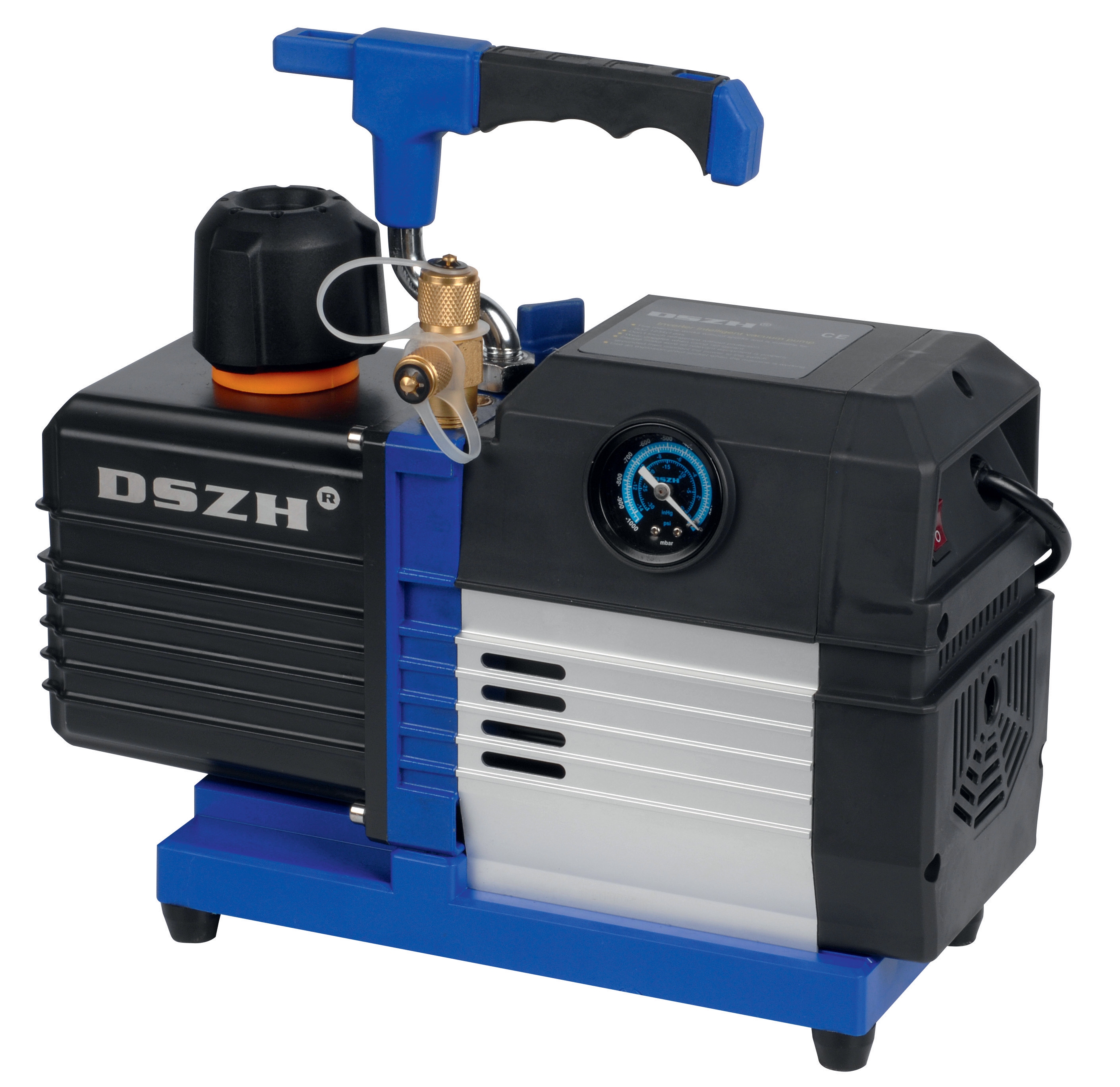
Singapore-based HVAC service teams report erratic refrigerant pressure measurements on systems using CBM Vacuum Pump 71 L/MIN units during evacuation procedures. Gauge readings fluctuate wildly between measurements taken minutes apart, despite stable ambient conditions and steady pump operation. Investigation reveals moisture contamination inside the gauge housing—common in tropical regions where relative humidity exceeds 80% and thermal cycling creates internal condensation. Solution: replacement with sealed, glycerin-filled gauge models and implementation of monthly visual inspection protocols to detect early seal degradation before operational impact occurs.
Scenario 3: Pressure Gauge Installation Orientation Errors
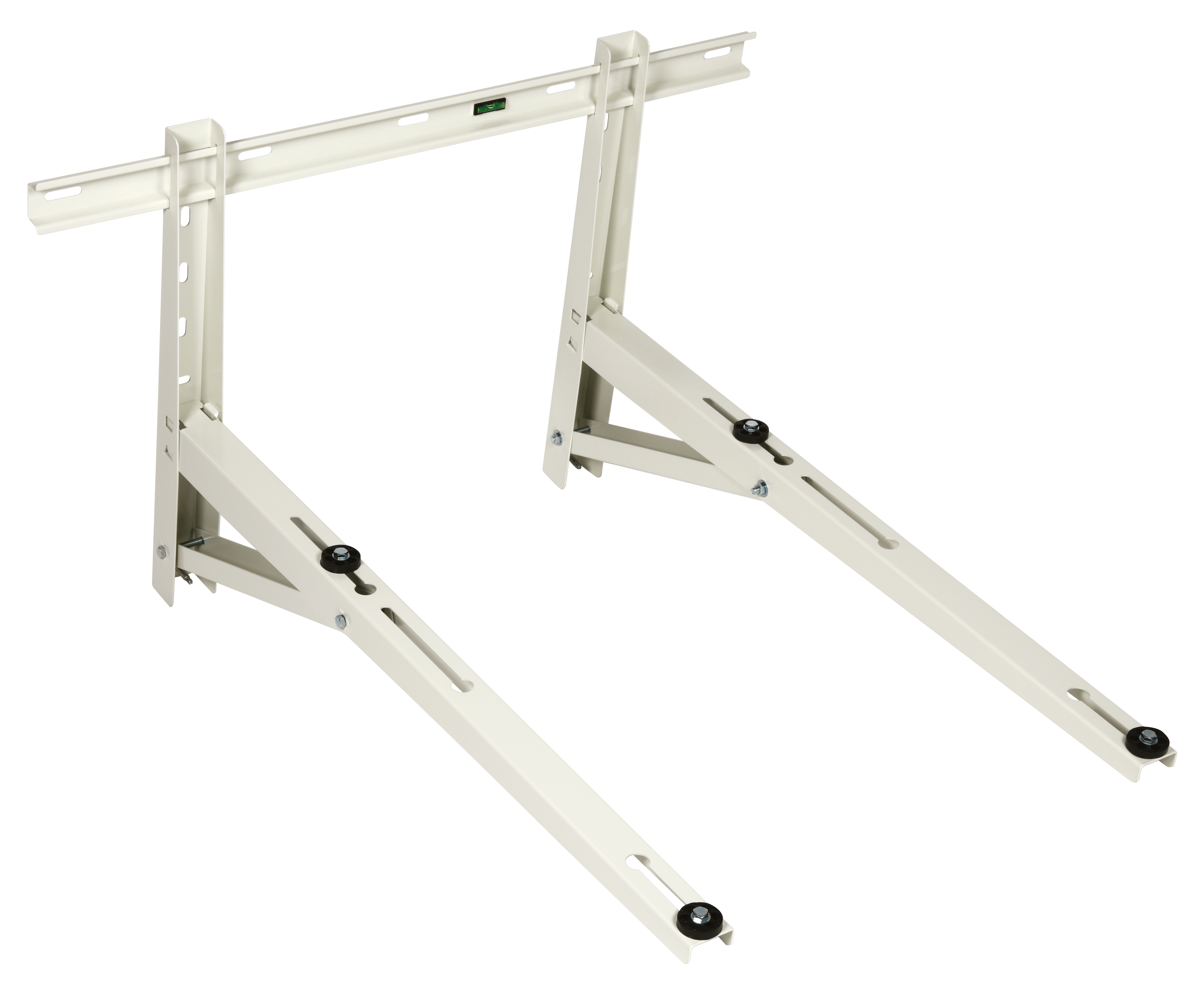
A facility reports consistent 15 bar pressure overestimation on a system fitted with a horizontal wall-mounted display gauge. Upon inspection, the gauge was installed in a tilted orientation (45° from vertical) due to space constraints near the CBM Wall Bracket 1000 mounting structure. Reorienting the gauge to vertical mounting eliminated the reading error. This scenario underscores the importance of verifying installation geometry during initial commissioning and periodic maintenance inspections.
Calibration Selection Criteria & Maintenance Best Practices
Gauge Selection for System Compatibility
Match gauge pressure range to system operating parameters with 25-33% headroom above maximum expected working pressure. For vacuum or low-pressure applications (below 10 bar), glycerin-filled gauges reduce reading noise and needle flutter. For high-pressure systems exceeding 200 bar, stainless steel construction resists corrosion and withstands pressure transients. The CBM Glycerin Stainless Steel Pressure Gauge combines both attributes, making it suitable for diverse industrial applications including pump discharge monitoring and HVAC system commissioning.
Environmental Adaptation Strategies
In tropical climates—particularly Singapore, Malaysia, and Southeast Asia—specify gauges with enhanced sealing (IP67 minimum) and stainless steel components to resist salt-air corrosion. Install protective gauge snubbers or damping restrictor valves on pulsating pressure lines to extend gauge service life by 40-60%. Implement quarterly visual inspections in high-humidity environments and semi-annual professional recalibration to maintain data integrity.
Documentation & Trending Protocols
Maintain calibration records documenting reference pressure source certification, test point readings, and acceptance criteria. Trending gauge readings over months or years reveals gradual drift patterns before critical accuracy loss occurs, enabling proactive replacement rather than crisis-driven downtime. Digital pressure transducers with datalogging capabilities complement mechanical gauges for critical monitoring applications.
Integration with System Diagnostic Workflows
Pressure gauge verification must precede all other troubleshooting activities. Inaccurate pressure data undermines diagnostic conclusions about pump performance, relief valve function, and circuit integrity. Teams should establish a standardized verification protocol: confirm gauge accuracy before attributing pressure anomalies to component malfunction. This disciplined approach prevents misdiagnosis and ensures maintenance actions address root causes rather than measurement artifacts.
When diagnosing pump system issues—particularly with high-performance units like the Interpump PUMP E3B2515I R operating at 250 bar—always verify pressure gauge calibration first. A single miscalibrated gauge has generated countless unnecessary bearing replacements, seal kit changes, and relief valve adjustments in industrial facilities worldwide.
For complex diagnostics involving electrical signals, use the CBM Automatic Multimeter MM420 to verify gauge transducer outputs and circuit integrity, ensuring measurement data flows reliably from gauge to monitoring systems or control logic. Combining mechanical gauge verification with electrical signal validation creates comprehensive diagnostic confidence.
Conclusion & Next Steps
Pressure gauge calibration and monitoring represent fundamental competencies for maintenance teams operating industrial systems across global markets. Systematic verification procedures, environmental adaptation strategies tailored to tropical or challenging climates, and disciplined documentation protocols ensure accurate pressure data drives reliable troubleshooting and preventive maintenance decisions.
Misaligned pressure gauges have unnecessarily driven billions of dollars in global industrial maintenance spending. By implementing the diagnostic procedures outlined in this guide, your team transforms pressure monitoring from a vulnerability into a strategic diagnostic asset.
Ready to optimize your facility's pressure monitoring capabilities? 3G Electric has served industrial customers globally since 1990, providing calibrated instrumentation, high-performance pumps, and integrated measurement solutions tailored to your operational environment. Contact our technical team to discuss pressure gauge verification protocols, calibration services, or equipment selection for your next project. Whether you're managing systems in Singapore, Southeast Asia, or worldwide industrial zones, we provide the expertise and product portfolio to ensure measurement accuracy and system reliability.