Oil Supply System Troubleshooting: Diagnosing Pump & Pressure Regulator Failures in Industrial Burner Systems
Industrial oil burner systems depend critically on reliable fuel supply mechanisms to maintain consistent combustion performance and operational safety. When oil supply systems fail, production halts and costly downtime accumulates rapidly. This troubleshooting guide addresses the most common failure modes in low-pressure and high-pressure oil pump systems, pressure regulators, and their associated components used throughout Singapore's industrial sector. By understanding how to systematically diagnose faults in fuel delivery units, maintenance technicians can reduce diagnostic time, minimize emergency repairs, and extend equipment lifespan. This article examines real-world failure patterns, technical specifications, and step-by-step diagnostic procedures applicable to modern oil burner installations.
Understanding Oil Supply System Architecture and Common Failure Points
Contemporary industrial oil burner systems operate on clearly defined pressure ranges and flow rates that must be maintained within tight tolerances. The fuel supply chain typically consists of four primary components: the suction side (tank connection to pump inlet), the pump unit with integrated pressure regulation, the discharge line with safety features, and the nozzle assembly that atomizes fuel for combustion. Each component presents specific failure modes that cascade through the system if left unaddressed.
Low-pressure pump systems, such as those found in oil supply equipment, operate between atmospheric pressure and approximately 10 bar for initial fuel transfer. Conversely, high-pressure pump systems deliver fuel at 50-500 bar depending on burner nozzle specifications and combustion air requirements. The pressure regulator—integrated within many modern pump units—automatically maintains discharge pressure within design parameters by bypassing excess flow back to the tank. This dual functionality creates interdependencies: if the regulator fails to open, pressure escalates; if it opens excessively, pressure drops below minimum combustion requirements.
Singapore's tropical climate introduces specific challenges to oil supply diagnostics. High ambient temperatures accelerate fuel viscosity changes, humidity promotes internal corrosion in pump chambers, and extended monsoon periods create condensation risks in fuel tanks. These environmental factors don't cause primary failures but dramatically accelerate degradation of marginal components. Technicians must account for climate-induced variations when interpreting performance baseline data.
The most common failure pattern involves gradual pressure loss combined with reduced fuel flow—typically indicating internal pump wear, regulator valve stiction, or suction line blockages. Secondary failures occur when pressure escalates uncontrollably, suggesting regulator spring failure or valve spool jamming. Understanding this architecture enables systematic isolation of the failing component.
Diagnostic Procedures for Oil Pump and Pressure Regulator Systems
Effective diagnostics require three parallel measurement streams: suction-side pressure, discharge-side pressure, and fuel flow rate. Begin by establishing baseline readings under normal operating conditions before any system shutdown. Modern systems should demonstrate the following characteristics: suction pressure between -0.2 and +0.5 bar (slight vacuum is normal), discharge pressure matching burner specifications (typically 8-12 bar for standard installations), and consistent flow rates within ±5% of rated capacity.
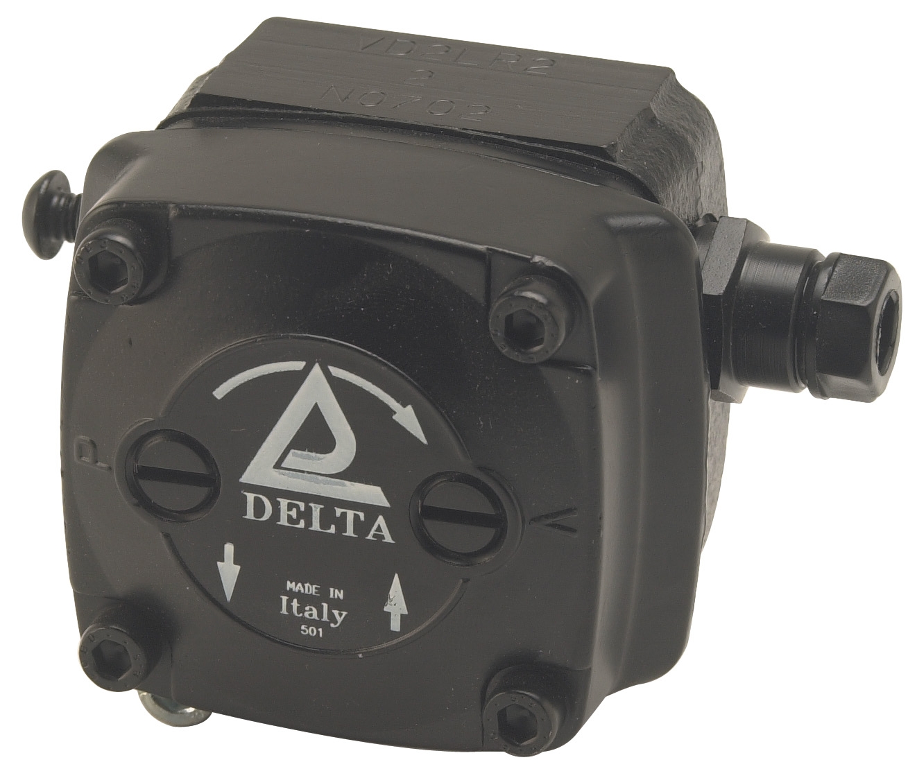
The CBM VD2 LR-2.2 low-pressure pump unit exemplifies standard oil burner fuel supply design with integrated pressure regulation and self-priming capability. This pump features high suction capability suitable for both single and dual-pipe fuel systems, critical for installations where the tank sits below the burner combustion chamber. When diagnosing VD2 series pumps, attach a calibrated pressure gauge to the discharge port—specifications mandate 200 mbar minimum system pressure for reliable atomization at the nozzle.
Pressure measurement must employ industrial-grade gauges with ±1.6% accuracy minimum. The CBM axial manometer provides stainless steel construction suitable for continuous monitoring in aggressive environments. This gauge features 0-400 mbar range with G1/4 female connection, directly compatible with standard pump discharge ports. Mount the gauge between the pump discharge and main supply line to capture transient pressure variations that digital readings alone may miss.
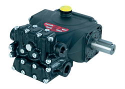
Flow diagnostics require timing fuel volume collection at the nozzle return line (on two-pipe systems) or measuring pressure drop across a calibrated orifice plate. For example, the Interpump PUMP 5015 R ATEX delivers 15 L/min at 500 bar—if measured flow drops below 12 L/min while discharge pressure remains at specification, internal pump wear or cavitation is occurring. This high-pressure pump (50 MPa / 7,250 psi) requires sealed test equipment; never perform pressure measurement on ATEX-rated pumps without appropriate certification.
Systematic diagnostic sequence: (1) Verify fuel tank level and condition—debris or water contamination immediately impacts pump performance; (2) Check suction line integrity—any air leaks reduce pump priming capability and create vapor lock; (3) Measure suction pressure with gauge attached directly at pump inlet; (4) Measure discharge pressure under normal burner operating load; (5) Compare results to pump nameplate specifications; (6) If discharge pressure is low, isolate whether regulator is opening excessively or pump is failing.
Real-World Troubleshooting Scenarios in Singapore Industrial Operations
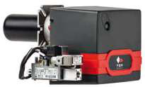
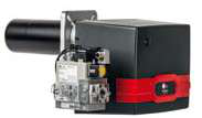
Scenario 1: A food processing facility operating an FBR X GAS XP 60 CE TC EVO gas/oil dual-fuel burner (_41) reports intermittent flame extinction and uneven heat distribution. The burner maximum output is 630 kW, but combustion chamber temperature sensors indicate actual output fluctuating between 50-70% of rated capacity. Initial diagnostics reveal discharge pressure oscillating between 7-11 bar instead of the required stable 9 bar. Root cause: the pressure regulator spring in the integrated fuel supply unit has weakened, causing hunting behavior where the regulator opens and closes continuously. Solution: replace the pressure regulator cartridge, not the entire pump unit—this represents a 60% cost reduction while restoring full system performance. After replacement, discharge pressure stabilized at 9.0±0.2 bar and flame geometry normalized.
Scenario 2: A petrochemical facility's oil supply system shows zero discharge pressure while the pump motor runs normally. Suction-side vacuum measurement reads -0.8 bar (excessive), indicating a blockage in the suction line. Technicians discovered the suction filter element completely saturated with diesel gelling—tropical humidity combined with temperature fluctuations caused paraffin crystallization. After filter replacement and suction line purging, the pump self-primed successfully and resumed normal operation. This case demonstrates why suction-line diagnostics must precede pump replacement decisions.
Scenario 3: A manufacturing facility using high-pressure Interpump TSX 15.150 415/50 multireg system experienced discharge pressure clamping at 150 bar when the system normally adjusts to 130 bar. The integrated total-stop valve malfunctioned, preventing normal pressure regulation. Digital pressure monitoring data showed zero flow after the valve closure point, confirming blockage rather than gradual leak. Valve cartridge replacement restored functionality, demonstrating the importance of understanding integrated component interdependencies in modern pressure-regulated pump systems.
Selection and Maintenance Best Practices for Oil Supply Systems
Preventive maintenance extends oil supply system lifespan by 40-60% compared to reactive failure-based repair cycles. Establish quarterly visual inspections of all fuel connections, monthly pressure logging at fixed operating conditions, and semi-annual gauge calibration verification. Document baseline pressure and flow data at system commissioning—this baseline becomes the diagnostic reference point for detecting degradation trends.
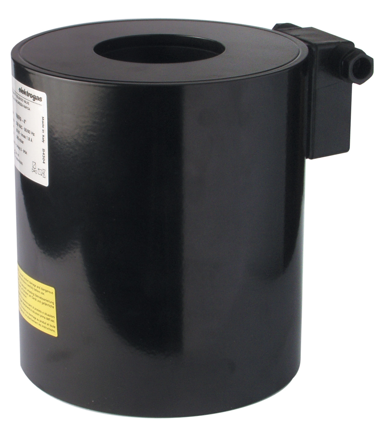
Component selection must account for Singapore's operating environment. Specify stainless steel gauge components rather than painted carbon steel—corrosion resistance proves essential in high-humidity maritime conditions. For solenoid-controlled systems, select 24V AC coils (such as CBM ELV93006, ) over 230V variants when possible, as lower voltage circuits demonstrate superior electromagnetic reliability and reduced RFI susceptibility in industrial electrical environments.
Fuel filtration represents the single most cost-effective preventive measure. Install duplex filter systems with automatic changeover valves and pressure differential indicators—this configuration permits filter element replacement without system shutdown. Maintain fuel storage tanks with breathable vent filters and drain water accumulation monthly. For two-pipe systems, verify return line backpressure remains below 0.5 bar; excessive return pressure indicates nozzle blockage or return line sizing issues rather than supply pump failure.
Connecting Technical Diagnosis to Equipment Replacement Decisions
When troubleshooting reveals confirmed pump failure, verify whether the integrated pressure regulator has failed simultaneously. Many technicians reflexively replace entire pump units; however, component-level repair often restores functionality at substantial cost savings. Request pump flow curves and pressure-flow characteristic graphs from the manufacturer when available. These data enable precise identification of whether failure is mechanical (worn internal components), hydraulic (regulator valve leakage), or connection-related (loose fittings causing air entrainment).
For sites requiring high availability, maintain spare pump units and regulator cartridges specific to each installed burner model. Given the critical nature of fuel supply systems, rapid component replacement proves more cost-effective than extended diagnostic cycles. However, ensure diagnostic data is captured before component replacement—this information informs root cause analysis and prevents recurrence of underlying installation issues.
Conclusion and Next Steps
Systematic oil supply system troubleshooting combines pressure measurement discipline, understanding of regulator operation principles, and awareness of environmental factors specific to Singapore's industrial sector. By following the diagnostic sequences outlined in this guide, maintenance teams can confidently isolate failing components and make informed repair-versus-replacement decisions. The products referenced throughout—from low-pressure VD2 series pumps to high-performance ATEX-rated pressure units—represent standard industrial equipment; however, their performance depends entirely on proper diagnostic methodology and informed maintenance decisions.
Oil supply system failures often appear sudden but result from cumulative degradation detectable through trending analysis. Implement pressure and flow logging systems to establish baseline behavior, review data quarterly, and replace components before catastrophic failure. For complex diagnostic situations or guidance on component selection for specific burner models operating in Singapore's environment, contact 3G Electric's technical team. Our experienced staff has supported industrial operations across Singapore since 1990 and maintains comprehensive inventory of maintenance and service components including solenoid coils, pressure gauges, and pump assemblies ready for same-day dispatch to minimize your operational downtime.