How to Select and Install Oil Supply Pumps for Industrial Burner Systems in Singapore
Oil supply pump selection is a critical decision in configuring industrial burner systems, yet many professionals overlook the technical parameters that determine system reliability and efficiency. In Singapore's demanding industrial environment, where uptime is non-negotiable and operating costs directly impact profitability, specifying the correct pump becomes essential. This guide walks through the selection criteria, technical specifications, and installation procedures for oil supply pumps used in conjunction with gas burner systems, solenoid valves, and pressure control equipment. Whether you're commissioning a new facility or retrofitting an existing system, understanding pump performance curves, pressure ratings, and compatibility requirements will ensure safe, compliant operation aligned with Singapore's industrial safety standards.
Understanding Oil Supply Pump Fundamentals in Burner Systems
Oil supply pumps serve as the heart of fuel delivery systems in industrial burners, converting electrical or mechanical energy into controlled fluid flow at precisely regulated pressures. In burner applications, these pumps must maintain consistent pressure despite fluctuations in fuel demand, system temperature, and valve resistance—a requirement that distinguishes them from general-purpose hydraulic pumps.
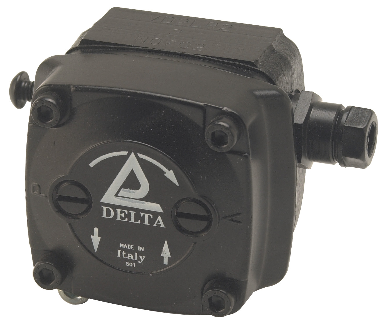
The CBM VD2 LR-2.2 low-pressure pump represents the standard for modern oil burner fuel units, engineered to EN 225 international standards. This pump design incorporates a compact footprint while delivering reliable suction capability and self-priming functionality—critical features for installations where fuel supply lines may experience air ingress or require extended suction distances. The VD series utilizes pressure-regulating mechanisms integrated into the pump body, eliminating the need for external regulation in many applications and simplifying system architecture.
Key operating principles include: (1) Pressure generation—the pump converts rotational mechanical input into positive displacement, building system pressure; (2) Flow regulation—integrated bypass or regulating valves automatically adjust displacement to maintain setpoint pressure regardless of demand fluctuations; (3) Thermal stability—fuel circulation and regulated return flow prevent pressure spikes from thermal expansion; (4) Cavitation prevention—high suction capability ensures adequate inlet pressure, protecting pump internals from erosion damage.
In Singapore's tropical environment, where ambient temperatures regularly exceed 30°C and humidity levels demand corrosion-resistant materials, pump selection must account for fuel viscosity changes across operating ranges. Lower viscosity in heated fuel reduces pump efficiency, requiring careful pressure setpoint calibration to maintain system performance. The pressure-regulating design of the VD2 series accommodates these variations through direct-acting regulating pistons that automatically adjust clearance flows, maintaining constant discharge pressure within ±0.5 bar across standard operating windows.
Technical Specifications and Product Selection for Oil Supply Applications
Selecting the appropriate pump requires matching four critical parameters: (1) Required flow rate, measured in liters per minute (L/min) or US gallons per minute (US gpm); (2) System pressure, expressed in bar, MPa, or PSI; (3) Inlet conditions, including available suction head and fuel temperature; (4) Duty cycle, encompassing run hours, start frequency, and thermal load.
The CBM VD2 LR-2.2 pump is optimized for low-pressure oil burner applications, delivering flow rates compatible with burners operating between 200 and 300 kW thermal output. This positioning makes it suitable for medium-scale industrial heating, process applications, and facility-level space conditioning. The "LR" designation indicates low-pressure regulation capability, typically 0.5–3.0 bar, appropriate for atomizing nozzles requiring consistent but modest pressure.
For higher-capacity installations or systems requiring elevated discharge pressures, larger displacement pumps become necessary. The Interpump PUMP 5015 R ATEX unit delivers 15 L/min at 500 bar (50 MPa / 7,250 PSI), developing 20 horsepower (14.7 kW) at 1,450 rpm. Despite this performance intensity, the pump weighs only 19.5 kg and maintains compact dimensions of 351.5 × 242.5 × 195.5 mm (L × W × H), enabling space-efficient integration in existing plant layouts. The ATEX certification indicates suitability for potentially explosive atmospheres—a requirement in certain Singapore industrial zones handling flammable fuels or powders.
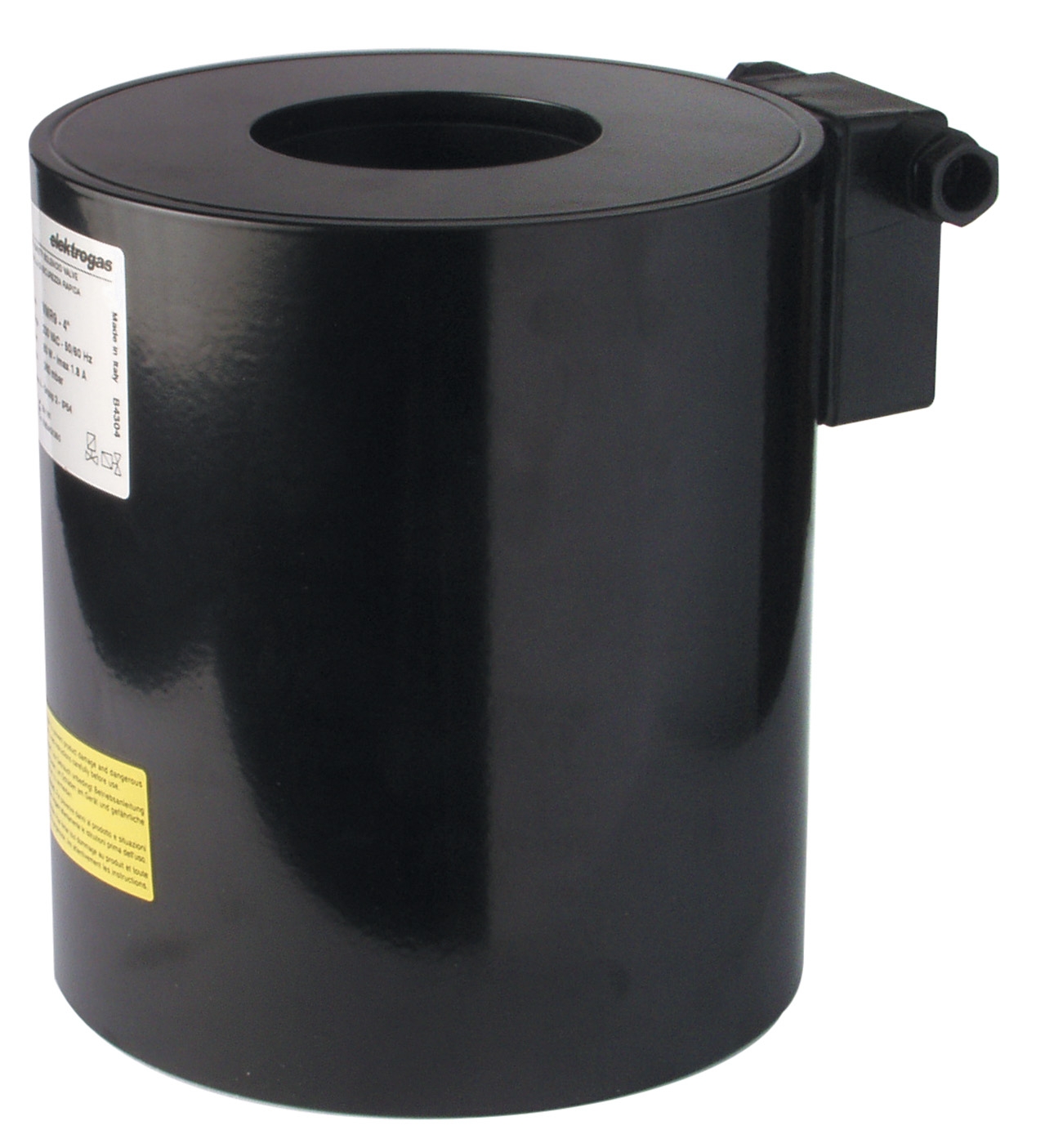
Complementing the pump assembly, solenoid valve coils provide electrically controlled fuel isolation and modulation. The CBM Coil 1930.1814 230V VML 2"1/2-3" 200mbar operates at 230V AC supply voltage, making it compatible with standard three-phase industrial electrical infrastructure throughout Singapore. The 200 mbar (0.2 bar) pilot pressure requirement indicates low-energy actuation—essential for rapid response and reliable operation at burner ignition. For lower-voltage applications or facilities using 24V control systems, the CBM Coil 24V AC for ELV7....2/4/6/8 provides identical functional performance at reduced supply voltage, simplifying integration with programmable logic controllers (PLCs) and automated burner management systems.
Pressure measurement and monitoring demand equal attention. The CBM Stainless steel axial manometer D63 0/+400Mbar provides visual confirmation of system pressure with ±1.6% accuracy across ranges up to 400 mbar. Stainless steel construction resists corrosion in the coastal and industrial environments common throughout Singapore, while the G1/4 connection point enables standard NPT or BSP integration into burner manifolds and fuel unit headers.
Step-by-Step Installation Procedure for Oil Supply Pump Systems
Step 1: System Design and Pressure Calculation
Begin by determining burner atomizing nozzle pressure requirements—typically 1.5–3.0 bar for pressure-jet burners or 0.2–0.5 bar for air-atomizing systems. Add 0.5–1.0 bar for line losses across piping, filters, and valve assemblies. This sum establishes the pump discharge pressure setpoint. Document all pressures in both bar and PSI for team reference.
Step 2: Pump Installation and Mounting
Position the pump on a vibration-isolating base to minimize noise transmission to building structure. Ensure suction line diameter is minimum 1" (25 mm) nominal, with total inlet length not exceeding 2 meters and vertical lift under 1 meter from fuel tank to pump inlet. Install a strainer with 150-mesh screen at the tank inlet to prevent particulate contamination. Verify fuel temperature will remain within 10–60°C under all operating conditions; apply external cooling if necessary in high-ambient installations.
Step 3: Solenoid Valve and Pressure Regulator Assembly
Mount the CBM solenoid valve coil downstream of the pump discharge, before the pressure regulator. If using the 230V VML coil, confirm three-phase 230V AC ±10% is available; for 24V applications, integrate a control transformer stepping down from site supply. Install the pressure gauge immediately downstream of the regulator setpoint port using a snubber valve to dampen pressure pulsations.
Step 4: Fuel Line Commissioning and Pressure Verification
Fill the fuel tank and bleed all air from pump inlet by manually priming or running the pump at low load. Activate the solenoid valve and observe pressure gauge rise. Adjust regulator setpoint to target pressure using the adjustment screw; typical setpoint is 2.5 bar for pressure-jet nozzles. Allow 15 minutes of running before confirming stable pressure within ±0.2 bar of setpoint.
Step 5: System Testing and Documentation
Operate the system through complete on-off cycles, verifying solenoid valve response time (typically 50–100 ms). Monitor fuel temperature at the pump outlet; if exceeding 50°C continuously, reduce system pressure or improve heat dissipation. Document all final pressure setpoints, coil voltage ratings, and electrical control signal polarities in the burner control documentation for future service reference.
Selection Criteria and Best Practices for Singapore Industrial Operations
Pump selection in Singapore must account for tropical operating conditions, regulatory compliance, and system integration with modern burner controls. Fuel compatibility remains paramount—diesel, heavy fuel oil (HFO), and light fuel oil (LFO) present different viscosity profiles. The CBM VD2 LR-2.2 pump handles all three, but viscosity changes with temperature demand careful regulator tuning. Specify pump displacement to deliver 1.5–2.0 times the nozzle flow requirement during normal operation; this excess flow returns through the regulator, ensuring consistent cooling and pressure stability.
Electrical integration requires matching coil voltage to site supply. Most Singapore industrial facilities operate 415V three-phase, 50 Hz; the 230V coils require a control transformer step-down, while 24V coils eliminate this requirement but add transformer cost. The marginal expense of a dedicated 24V control power supply often proves justified by improved reliability and faster solenoid response in safety-critical ignition circuits.
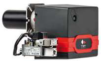
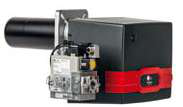
Pressure safety margins prevent system overpressure damage. Set the pump regulator 0.5 bar below any downstream safety relief valve; this ensures the regulator limits pressure before safety devices activate, reducing wear on safety equipment. For systems using the FBR X GAS XP 60 CE TC EVO burner (which delivers 232–630 kW thermal output), fuel delivery pressure must remain stable within a 0.3 bar band to prevent flame instability and combustion inefficiency.
Preventive maintenance cycles extend equipment life and prevent unexpected shutdowns. Inspect suction strainers monthly; clean or replace when pressure drop across the strainer exceeds 0.3 bar. Verify solenoid coil continuity annually using a multimeter; a reading above 500 ohms indicates moisture ingress or insulation breakdown, necessitating coil replacement. Check pump shaft coupling alignment quarterly; excessive runout causes premature bearing wear and increases noise levels.
Conclusion and Next Steps
Proper oil supply pump selection and installation form the foundation of reliable industrial burner operation throughout Singapore. By systematically evaluating flow requirements, pressure setpoints, electrical integration, and environmental factors—and by documenting all commissioning parameters—you create systems that operate safely, efficiently, and with minimal downtime. The technical products discussed here, including the CBM VD2 LR-2.2 pump, CBM solenoid valve coils, and pressure instrumentation, represent proven solutions deployed across Singapore's industrial base.
3G Electric has served Singapore's industrial sector since 1990, supplying these specialized components alongside technical expertise to ensure successful system implementation. Whether you're troubleshooting an existing installation, specifying equipment for new construction, or training personnel on burner system operation, our technical team provides the product knowledge and application support needed to optimize performance. Contact 3G Electric today to discuss your specific burner system requirements, verify product compatibility with your operating conditions, and access detailed technical documentation for all components featured in this guide.