How to Configure Gas Burner Systems with Solenoid Valves in Singapore Industrial Applications
Gas burner systems are critical infrastructure in many Singapore-based industrial facilities, from manufacturing plants to commercial heating applications. Proper configuration of solenoid valves—the electromechanical gatekeepers of fuel flow—determines system reliability, safety, and operational efficiency. This technical guide walks industrial professionals through the essential configuration process, providing data-driven insights and real-world equipment specifications to ensure your gas supply system operates within optimal parameters. Whether you're commissioning a new burner installation or troubleshooting an existing system, understanding solenoid valve integration with burner control systems is fundamental to maintaining safe and efficient operations.
Understanding Solenoid Valve Function in Gas Burner Systems
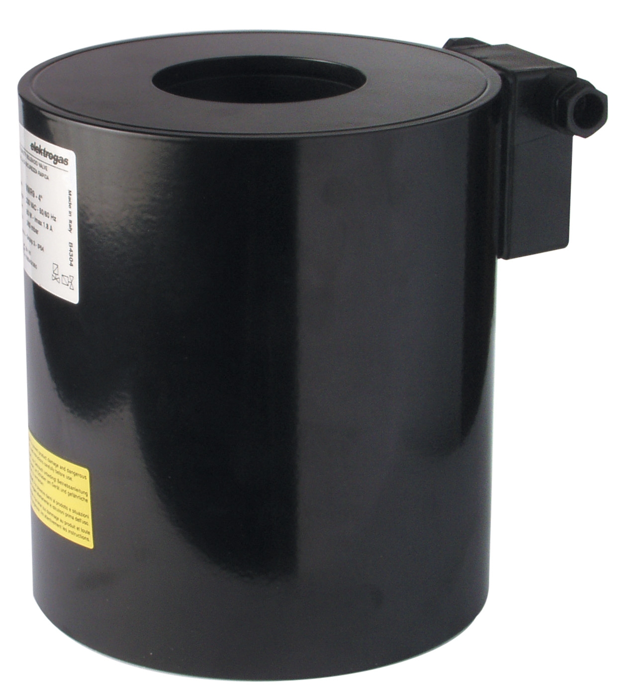
Solenoid valves serve as the primary control mechanism for gas flow in burner systems, converting electrical signals into precise mechanical valve actuation. In industrial gas burner applications, these valves must respond rapidly to control signals while maintaining tight sealing to prevent unintended gas leakage. The solenoid coil—essentially an electromagnet—energizes when voltage is applied, generating a magnetic field that pulls an armature and opens the valve seat, allowing pressurized gas to flow toward the burner nozzle.
The electrical supply to the solenoid coil is critical. Most industrial installations in Singapore operate on 230V AC single-phase or 24V AC control circuits. The CBM Coil 1930.1814 230V VML, rated for 2½–3" valve bodies at 200mbar operating pressure, represents a standard configuration for medium-pressure applications. For lower-voltage control systems requiring galvanic isolation or multiple valve control, the CBM 24V AC solenoid coil for ELV7 series valves provides reliable actuation across a range of burner sizes.
The pressure differential across the valve—the difference between inlet and outlet pressure—directly affects solenoid coil performance. Valves designed for 200mbar operation require specific coil designs to overcome pressure forces and achieve reliable opening within 0.5 seconds. Higher-pressure systems demand more robust coil configurations. Understanding your system's operating pressure is the foundation of correct solenoid valve selection and configuration.
Technical Specifications and Burner System Integration
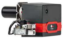
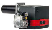
The FBR X GAS XP 60 CE TC EVO burner represents a high-capacity industrial solution, delivering between 232 kW minimum and 630 kW maximum thermal output with a 250mm nozzle assembly. This burner requires coordinated control from multiple solenoid valves managing gas supply pressure, fuel cutoff, and ignition circuits. The burner's three-phase electrical supply (400V typical in Singapore installations) powers the fan motor and control transformer, which steps voltage down for solenoid circuit operation.
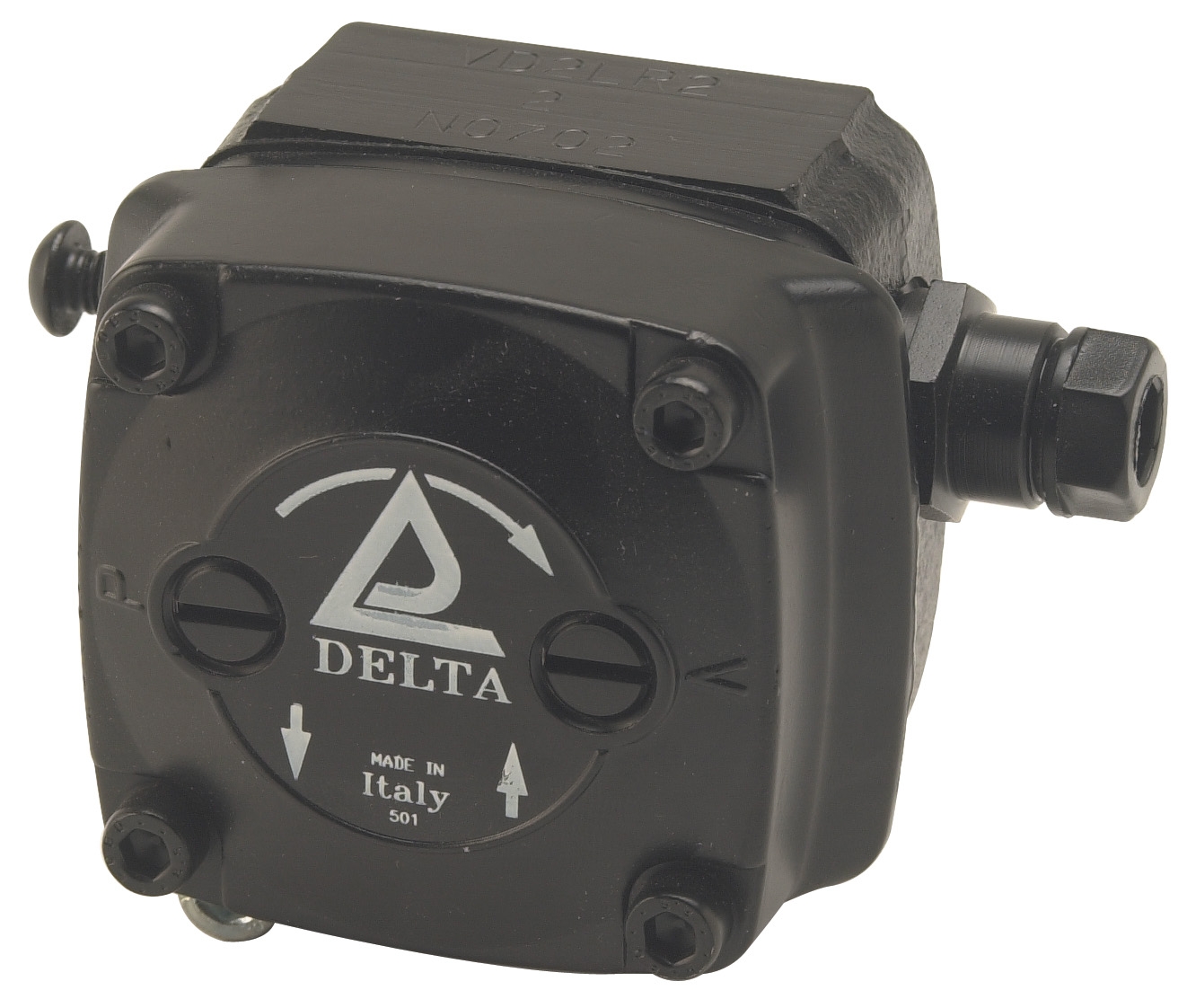
For fuel supply systems feeding high-capacity burners, pressure regulation is paramount. The CBM VD2 LR-2.2 low-pressure pump is specifically engineered as an oil burner fuel unit with integrated pressure regulation, conforming to EN 225 international standards for burner-mounted equipment. While primarily specified for oil applications, this pump's design principles—high suction capability, self-priming operation, and suitable pressure characteristics for both single and dual-pipe fuel systems—inform understanding of fuel delivery requirements that parallel gas system pressurization.
Interpump's W5015 R ATEX pump demonstrates high-pressure capability relevant to industrial gas systems requiring boost pressure: 500 bar (50 MPa / 7,250 psi) at 1,450 rpm with 20 hp (14.7 kW) input power and 15 L/min flow capacity. While ATEX-certified for hazardous area operation, this pump illustrates the engineering principles of pressure vessels and supply systems that must interface safely with gas solenoid valve control circuits. Pressure gauges—such as the CBM stainless steel axial manometer rated for 0–400 mbar with ±1.6% accuracy—provide essential feedback for system commissioning and maintenance verification.
Step-by-Step Solenoid Valve Configuration Process
Step 1: Verify System Operating Pressure — Before any solenoid valve installation, measure your gas supply pressure using a calibrated manometer. Record the inlet pressure and maximum system pressure. For the CBM 1930.1814 valve rated at 200mbar, confirm your system pressure does not exceed this specification. Higher-pressure systems require alternative valve selections.
Step 2: Select Appropriate Solenoid Coil Voltage — Coordinate with your burner control system design. Determine whether your control circuit operates 230V AC (commonly available from transformer secondary in Singapore three-phase installations) or 24V AC (galvanic isolation standard). The CBM 1930.1814 coil fits 230V applications; the CBM ELV7 24V AC coil supports 24V control circuits. Order the correct coil—attempting to retrofit incorrect voltage will cause coil failure and system malfunction.
Step 3: Verify Valve Body and Port Size Compatibility — The CBM 1930.1814 accommodates 2½–3" valve bodies. Measure your existing valve body nominal diameter or confirm new valve procurement specifications. Thread connections (typically NPT or BSP in Singapore industrial equipment) must match your piping system. Verify with technical drawings before installation.
Step 4: Install Solenoid Coil with Proper Orientation — Position the coil vertically when possible, with the connector pointing downward. This orientation minimizes moisture accumulation. Ensure the valve lever—if applicable—moves freely and isn't mechanically restricted. Secure connector with the supplied bracket to prevent vibration-induced loosening.
Step 5: Conduct Electrical Continuity and Insulation Testing — Before energizing, measure resistance between solenoid terminals using a multimeter. For 230V coils, expect 4–8 kΩ resistance at ambient temperature. Insulation resistance (measured to ground/case) should exceed 5 MΩ. If readings are outside specification, replace the coil.
Step 6: Pressure Test and Functional Verification — With gas supply isolated, energize the solenoid circuit momentarily (2–3 seconds). You should hear a distinct clicking sound as the armature engages. De-energize and listen for a return click. Under no-load pressure (system isolated), actuation should occur within 0.5 seconds. Repeat five times to confirm consistency before opening fuel supply valves.
Selection Criteria and Configuration Best Practices
Solenoid valve selection depends on five critical parameters: inlet pressure, outlet pressure, flow rate requirements, fluid type (gas composition), and electrical supply voltage available. Gas valve selection in Singapore industrial applications must account for local gas utility specifications—typically natural gas (methane) at 20–25 mbar inlet pressure for residential/commercial supply, or higher pressures (100–500 mbar) for industrial installations with onsite pressure regulation.
Pressure differential (ΔP) across the solenoid valve directly impacts coil performance. Direct-acting solenoids—where the coil directly lifts the valve seal—function reliably up to approximately 3 bar differential. Pilot-operated designs, using controlled leakage to generate pressure differential across the main valve seal, handle higher pressures (up to 16 bar or greater) with lower coil power consumption. For your burner system, confirm whether your valve is direct-acting or pilot-operated before selecting coil specifications.
Environmental factors matter significantly in Singapore's tropical climate. Humidity and salt-air exposure (particularly in coastal industrial zones) demand stainless steel or nickel-plated components. The CBM coil specifications include ingress protection ratings (typically IP55 or IP67); ensure adequate protection for your installation location. Install solenoid coils in protected junction boxes with corrosion-resistant fittings, especially for outdoor or marine-adjacent facilities.
Flow capacity must match burner gas consumption. Calculate required flow rate by dividing maximum burner thermal output (kW) by gas energy density (typically 10 kWh/m³ for natural gas). For the FBR X GAS XP 60 burner at 630 kW maximum output, required gas flow approaches 63 m³/hour. Your solenoid valve must handle this flow without excessive pressure drop; most industrial solenoid valves sized for 2½–3" connections support 50–150 m³/hour flows, adequate for typical burner applications.
Why Proper Configuration Matters for Singapore Industrial Operations
Misconfigured solenoid valves create significant operational and safety risks. Undersized coils may open sluggishly, delaying gas ignition and creating unburned gas accumulation—a serious explosion hazard. Oversized coils waste electrical power and generate excessive electromagnetic noise. Incorrect voltage selection causes immediate coil burnout, typically within seconds of energization, requiring emergency replacement and production downtime.
Singapore's stringent safety regulations, including compliance with PSB (Professional Engineers Board) standards and SS 638 (Gas Safety Code), mandate proper burner system commissioning. Third-party validation by licensed technicians is often required. Maintaining detailed configuration records—solenoid coil model, voltage rating, installation date, pressure test results—provides essential documentation for regulatory audits and insurance compliance.
Preventive maintenance extends solenoid valve service life. Annual inspection of coil connections for corrosion, testing of electrical continuity, and functional cycling under no-load conditions cost minimal resources but prevent catastrophic failures. Singapore industrial equipment distributors like 3G Electric stock replacement coils (CBM 1930.1814, CBM ELV93006) for rapid deployment when failures occur.
Conclusion and Next Steps
Configuring gas burner solenoid valves demands precise attention to electrical specifications, pressure parameters, and mechanical compatibility. By following this technical guide—verifying operating pressure, selecting correct voltage ratings, confirming valve body compatibility, conducting thorough testing, and adhering to best-practice installation and maintenance procedures—industrial professionals can ensure safe, reliable gas burner operation throughout Singapore's demanding industrial environment.
Whether you're commissioning a new FBR X GAS XP 60 burner system, upgrading solenoid controls on existing equipment, or troubleshooting valve performance issues, the products and technical expertise are readily available. Contact 3G Electric today to discuss your specific burner system requirements. Our authorized industrial equipment specialists have served Singapore's manufacturing and commercial sectors since 1990, offering comprehensive product selection, technical consultation, and rapid logistics support. With access to CBM solenoid coils, Interpump pumps and controls, and complementary pressure measurement instruments, we provide complete solutions for industrial gas system configuration and maintenance. Reach out now to ensure your installation meets safety standards and operational excellence.