How to Maintain Gas Valve Solenoid Coils in Industrial Systems: A Technical Guide for Singapore Operators
Solenoid valve coils are critical components in industrial gas burner systems, controlling the flow of fuel and gas with electromagnetic precision. In Singapore's tropical climate and demanding industrial environments, proper maintenance of these components is essential to prevent system failures, maintain operational efficiency, and ensure safety compliance. This guide provides industrial professionals with comprehensive technical procedures for maintaining solenoid coils, identifying degradation, and implementing preventive measures that extend equipment lifespan and optimize performance in demanding applications.
Understanding Solenoid Valve Coil Function and Failure Modes
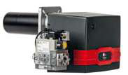
A solenoid coil operates by converting electrical energy into a magnetic field that actuates a plunger mechanism, controlling valve opening and closing. In gas valve systems used with equipment like the FBR X GAS XP 60 CE TC EVO burner, the coil must respond reliably across thousands of cycles, handling thermal stress, electrical transients, and environmental contamination.
Common failure modes in solenoid coils include:
- Insulation breakdown: Moisture ingress and thermal cycling degrade wire insulation, causing short circuits or resistance increase
- Coil winding fractures: Mechanical vibration and thermal expansion create stress points where wire breaks internally
- Debris accumulation: Ferrous particles from system corrosion lodge on the coil plunger, preventing proper movement
- Voltage fluctuations: Inconsistent electrical supply (particularly important in Singapore's variable industrial networks) causes incomplete magnetic field generation
- Thermal fatigue: Repeated heating cycles in tropical environments weaken coil materials and solder joints
The CBM ELK Coil series, including models like the CBM Coil 1930.1814 230V VML 2"1/2-3" 200mbar, represents standard specifications for medium-pressure applications. These 230V coils are engineered to 50Hz operation standard in Singapore, with 200mbar pressure rating suitable for gas valve applications. Similarly, the CBM Coil 24V AC for ELV7 series provides lower-voltage alternatives for integrated control systems.
Understanding these failure mechanisms allows operators to implement targeted maintenance that prevents catastrophic failures and maintains system responsiveness.
Technical Specifications and Component Diagnostics
Effective maintenance begins with understanding the electrical and mechanical specifications of your installed coils. The CBM ELK26121 operates at 230V with a 2.5" to 3" valve body range and 200mbar pressure rating—critical parameters that must be verified during maintenance to ensure compatibility with your gas delivery system.
Diagnostic procedures require specialized equipment to measure coil condition accurately:
Resistance Testing: Use a calibrated digital multimeter to measure coil resistance. A significant increase (typically >15% above nameplate specifications) indicates insulation degradation or internal fractures. For the 230V CBM coils, expected resistance ranges should be documented during initial commissioning and compared against current measurements. Resistance trending reveals progressive deterioration before catastrophic failure.
Insulation Resistance Testing: Megohm meters measure insulation breakdown between coil windings and the metal frame. Values below 10MΩ suggest moisture contamination or insulation failure and warrant immediate coil replacement. This test is particularly important in Singapore's high-humidity environment, where condensation can accumulate inside valve enclosures.
Voltage Drop Measurement: When the coil is energized (under safe test conditions), measure actual voltage at the coil terminals. Voltage drops exceeding 10% suggest wiring issues or power supply problems that reduce magnetic force and slow valve response times.
For integrated burner systems like the FBR X GAS XP 60 CE TC EVO, which operates with a maximum output of 630 kW and minimum of 232 kW, solenoid coil condition directly impacts fuel control precision and combustion efficiency. The burner requires reliable fuel valve actuation across its full power range; coil degradation causes hesitation during load changes and increases emissions.
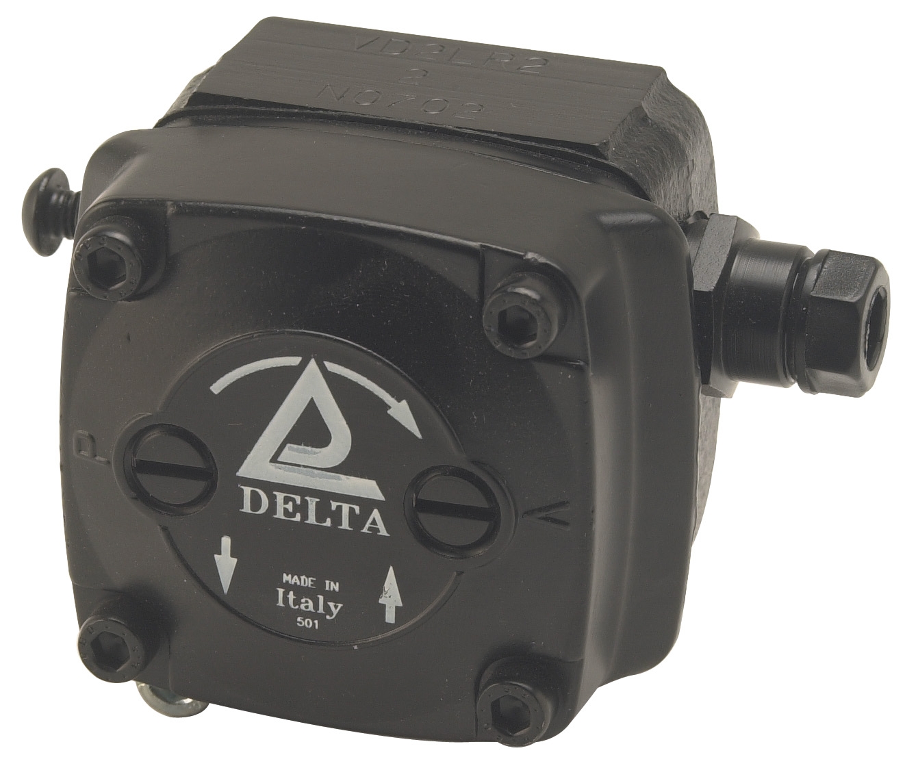
For fuel oil systems using the CBM VD2 LR-2.2 low-pressure pump, proper solenoid valve maintenance ensures consistent fuel delivery pressure and prevents pump cavitation. The pump's pressure-regulating design depends on solenoid valves to maintain optimal operating conditions.
Step-by-Step Solenoid Coil Maintenance Procedure
Step 1: Safety Isolation
Isolate all electrical power to the system at the main disconnect. Wait 5 minutes to ensure capacitors discharge fully. Verify power is off using a non-contact voltage tester. Lock out/tag out the isolation point and notify all personnel.
Step 2: Visual Inspection
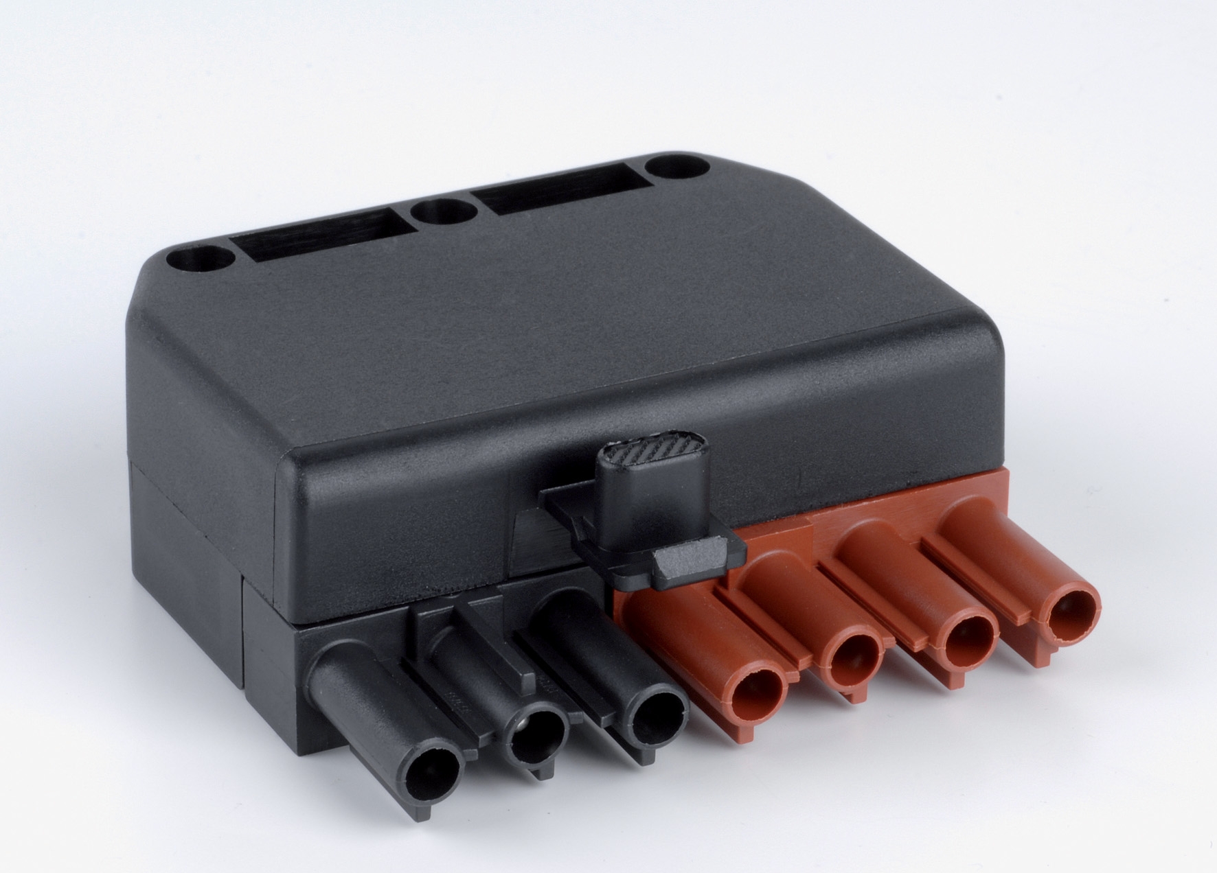
Examine the coil exterior for moisture accumulation, corrosion, and debris. Check connector terminals (such as the CBM 7 pole male connector, SKU: BRU20936) for oxidation or loose contacts. Inspect the coil mounting for vibration damage or physical impact. Document all visible damage with photographs.
Step 3: Electrical Testing
Using a calibrated digital multimeter, measure DC resistance between the coil terminals. Record the value and compare to baseline specifications. Document voltage rating (230V, 24V AC, etc.) and note any corrosion on connector pins that would increase contact resistance.
Step 4: Mechanical Inspection
With power still isolated, manually move the valve stem (where accessible) to verify smooth plunger movement. Resistance indicates stuck plungers caused by debris or corrosion. Do not force; if resistance is present, the coil assembly likely requires removal for cleaning or replacement.
Step 5: Environmental Check
Inspect enclosure seals and gaskets for deterioration. In Singapore's tropical climate, high humidity and salt-laden air near coastal facilities accelerate corrosion. Replace degraded gaskets and apply appropriate corrosion inhibitor to exposed metal surfaces. Ensure drainage holes in valve enclosures remain clear.
Step 6: Documentation and Scheduling
Record all measurements, observations, and actions taken. Compare baseline data to previous maintenance records to identify trends. Schedule replacement of coils showing >10% resistance increase or insulation degradation before they fail during operation.
Selection Criteria and Best Practices for Coil Maintenance
When maintaining or replacing solenoid coils, several technical criteria guide proper selection:
Voltage Compatibility: Confirm the installed voltage (230V, 24V AC, or others) matches your facility's electrical supply. The CBM ELK26121 operates at 230V 50Hz, standard for Singapore industrial installations. The CBM ELV93006 provides 24V AC alternatives for low-voltage control circuits. Voltage mismatches cause coil overheating or insufficient magnetic force.
Pressure Rating Match: The CBM Coil 1930.1814 is rated for 200mbar at 2.5-3" valve bodies. Verify your system's actual operating pressure and select coils rated at least 25% above peak operating pressure to prevent magnetic chattering and premature wear.
Connector Type Verification: Ensure replacement coils use identical connector configurations to existing wiring. Mixing connector standards increases installation errors and maintenance time. Document your connector type (such as the 7-pole standard) during initial system commissioning.
Environmental Sealing: For installations in high-humidity environments or areas with salt spray exposure (common in Singapore), specify coils with enhanced sealing ratings (IP67 minimum). Superior gaskets and potting compounds resist moisture ingress and extend coil lifespan significantly.
Preventive Replacement Schedule: Establish maintenance intervals based on operating hours, not just calendar time. Industrial systems operating continuously (as with the FBR X GAS XP 60 CE TC EVO burner system) warrant coil inspection every 2000 operating hours and replacement every 5000 hours or upon detecting >10% resistance increase.
Spare Parts Inventory: Maintain emergency stock of commonly used coils in your facility to minimize downtime. The investment in spare CBM ELK and ELV coils is recovered rapidly through reduced emergency replacement costs and maintained production continuity.
Integration with Complete System Maintenance
Solenoid valve coils operate within broader systems that require coordinated maintenance. In fuel oil systems using the CBM VD2 LR-2.2 pump, the fuel unit's pressure regulation depends directly on solenoid valve performance. Degraded coils cause pressure instability that damages pump internals and reduces burner efficiency. Similarly, in gas burner systems, solenoid valve reliability ensures precise fuel control and safe ignition sequences across the 232-630 kW operating range of industrial burners.
Document solenoid coil condition as part of comprehensive maintenance and service programs. Integrate electrical testing with mechanical system inspections and fuel delivery verification for complete system diagnostics.
Conclusion and Next Steps
Maintaining solenoid valve coils through systematic inspection, electrical testing, and preventive replacement ensures reliable operation of critical industrial gas and fuel systems. In Singapore's demanding industrial environment, where equipment operates continuously and unplanned downtime carries substantial costs, disciplined coil maintenance prevents failures that compromise safety and production efficiency.
The technical procedures outlined—from resistance testing to environmental sealing verification—provide a framework for operators to extend component lifespan, optimize system performance, and maintain compliance with industrial safety standards. By understanding failure modes and implementing data-driven maintenance decisions, industrial professionals maximize equipment reliability while controlling long-term operational costs.
If you operate the FBR X GAS XP 60 CE TC EVO burner system or fuel systems using CBM components in Singapore, contact 3G Electric for professional guidance on solenoid coil maintenance, component selection, and emergency replacement stock. Our technical team has served Singapore's industrial sector since 1990 and understands the specific challenges of maintaining industrial equipment in tropical environments. We stock the complete range of CBM solenoid coils, connectors, and diagnostic equipment required for comprehensive system maintenance. Reach out to discuss your facility's specific needs and establish a preventive maintenance program that delivers measurable improvements in equipment reliability and operational efficiency.