How to Diagnose and Replace Industrial Pump Components: A Global Maintenance Guide for Engineers
Industrial pumps are critical infrastructure in manufacturing, HVAC, and fluid transfer operations worldwide. Unlike the existing guides focusing on pump inspection methodologies and pressure regulation systems, this article takes a component-level approach—helping procurement and purchase engineers diagnose individual pump failures, understand when replacement is necessary, and execute safe replacement procedures using modern diagnostic tools. Whether you're managing facilities in Singapore, North America, or Europe, understanding how to identify failing pump components before catastrophic breakdown occurs can reduce downtime by 40% and extend equipment life by years. This guide walks through practical diagnostic workflows, component specifications, and step-by-step replacement procedures.
Understanding Pump Component Failure Modes
Industrial pumps operate under high-stress conditions, and component failure rarely occurs without warning signs. The key is recognizing these signals before they escalate into system shutdowns. Pump components typically fail through three mechanisms: mechanical wear (bearing degradation, seal failure), fluid contamination (particle buildup reducing efficiency), and cavitation damage (pressure inconsistency causing internal erosion).
Mechanical wear manifests as increasing vibration, audible noise changes, and temperature elevation. Bearing wear creates a grinding or squealing sound as metal-to-metal contact increases. Seal degradation results in fluid leakage around the pump housing, which you'll notice as oil spots or drips beneath the equipment. Cavitation—one of the most destructive failure modes—occurs when inlet pressure drops below the fluid's vapor pressure, creating vapor bubbles that collapse violently inside the pump. This phenomenon produces a distinctive clicking or crackling sound and causes pitting on internal surfaces.
Fluid contamination reduces pump efficiency incrementally. Particulates accumulate in clearances, increasing friction and heat generation. You'll notice this as gradual pressure drops, higher motor current draw, and elevated operating temperatures. The critical insight for procurement engineers: these failure modes overlap. A pump showing pressure loss and elevated temperature may have contaminated fluid, worn bearings, or both. Effective diagnosis requires systematic evaluation using both visual inspection and precision measurement tools.
Diagnostic Tools and Technical Specifications for Modern Pump Assessment
Effective pump diagnostics requires a toolkit combining visual inspection, pressure measurement, and electrical verification. At the core of any maintenance program should be precision instrumentation capable of measuring system performance against baseline specifications.
For pressure-based systems, a CBM glycerin stainless steel pressure gauge provides reliable, real-time pressure readings essential for diagnosing performance degradation. These gauges withstand harsh industrial environments and offer accuracy within ±1.6% of full scale. When monitoring Interpump pump models, establish baseline readings during commissioning—typically between 250-275 bar for standard industrial applications—then compare monthly readings to identify drift patterns that indicate component wear.
Electrical diagnostics require a CBM automatic multimeter for motor current analysis and voltage verification. Rising motor amperage (while flow and pressure remain constant) indicates increasing internal friction from bearing wear or fluid contamination. The multimeter should measure AC/DC current, voltage, and resistance across a range suitable for industrial motor circuits (typically up to 600V AC).
For safety-critical work, a CBM non-contact voltage detector enables pre-maintenance electrical verification without direct contact. This tool is essential before disconnecting motor leads, preventing accidental shock and equipment damage.
Real Interpump pump specifications serve as your diagnostic baseline. The Interpump E3B2515 series (available in multiple configurations) operates at 250 bar with a flow rate of 15 L/min at 1450 rpm. Motor power is 7.13 kW. If your pump delivers 12 L/min at the same pressure and rpm, you've lost approximately 20% flow—a red flag for internal wear. Component-level diagnostics then pinpoint whether the issue originates in the impeller, inlet manifold, or discharge valve.
Step-by-Step Pump Component Replacement Procedure
Before beginning replacement work, perform these verification steps:
- De-energize the system: Lock out the motor using your facility's lockout/tagout (LOTO) procedure. Verify power isolation with your non-contact voltage detector at the motor terminals and control circuit.
- Isolate and depressurize: Close inlet and discharge isolation valves. Open vent valves on the pump housing to release residual pressure. Allow 10 minutes for pressure equalization, then verify with your pressure gauge that the system reads zero bar.
- Drain residual fluid: Position a container beneath the pump. Open the lowest drain valve on the pump housing. Collect all fluid for proper disposal per local environmental regulations. Note the fluid color, smell, and condition—dark, burnt-smelling fluid indicates overheating and possible internal damage beyond component replacement.
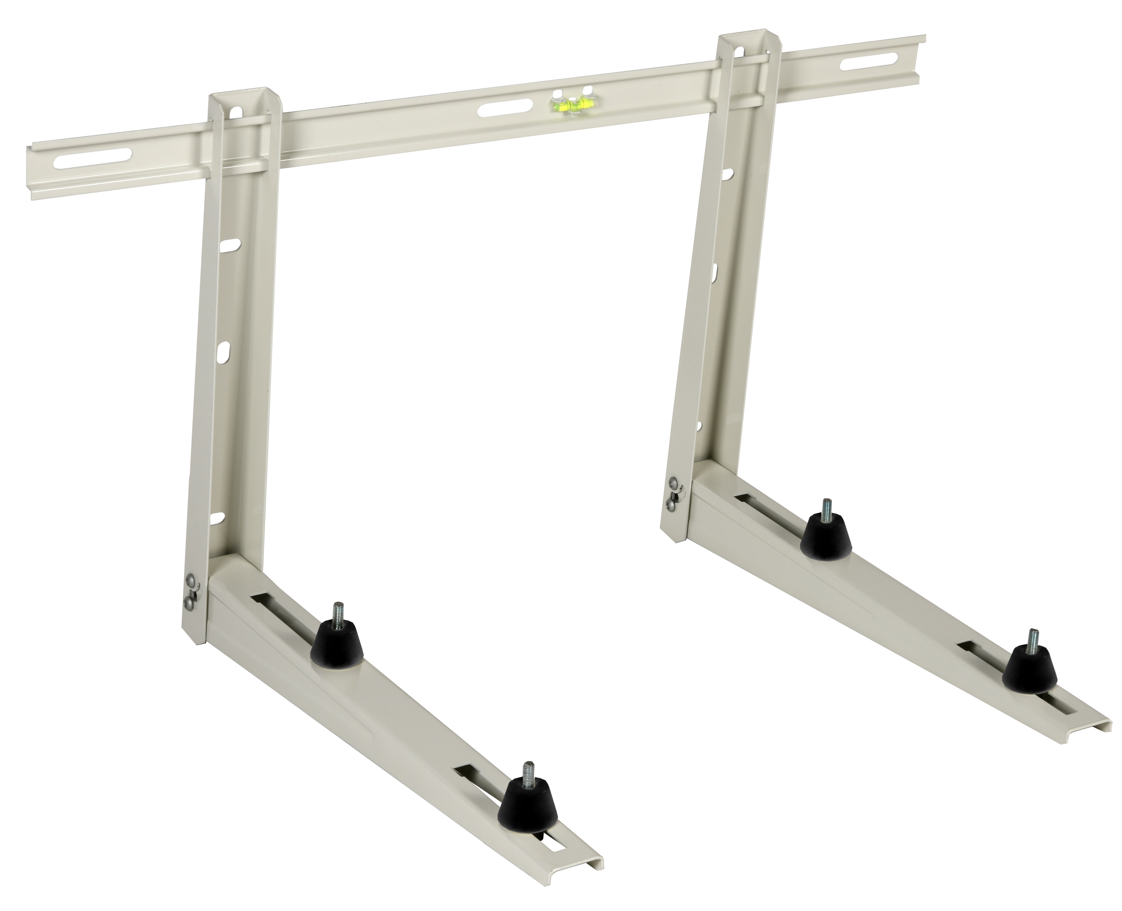
- Remove the pump from its mounting: For horizontally-mounted pumps using a CBM wall bracket (available in 400mm, 450mm, and 550mm lengths with load ratings up to 150 kg), unbolt the bracket attachment points. Have a helper support the pump weight. For cart-mounted systems, position your CBM X-Cart support (rated for 300L) beneath the pump for safe lowering.
- Document the installation: Before disconnecting piping, photograph the configuration and note all connection points. Label all hoses with painter's tape identifying inlet, discharge, and drain lines. Disconnect motor leads only after verifying isolation. Use your multimeter to confirm zero voltage across the motor terminals.
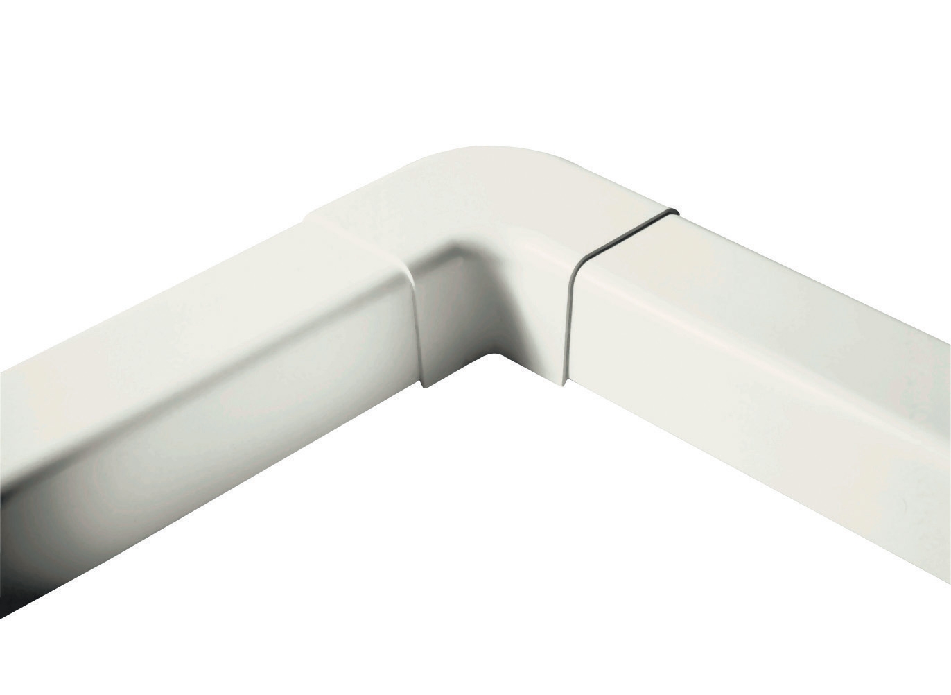
- Install replacement components: For systems requiring piping modifications, use CBM 90° flat elbows (60mm) to redirect flow while maintaining compact installation footprint. Install new seals on all mating surfaces using the gasket material specified in your pump documentation.
- Perform test assembly: Reconnect all lines hand-tight first. Verify alignment by rotating the pump shaft by hand (power still off)—resistance indicates misalignment. Tighten fittings incrementally in a star pattern to ensure even seating.
- Refill and bleed: Pour fresh fluid (matching the original specification) into the inlet port while hand-rotating the shaft. This distributes fluid through internal channels and displaces air. Continue until fluid appears at all vent points, then close vent valves.
- Energize and verify: Restore electrical power. Start the pump at 25% load (if your system has a modulating control like the FBR GAS X5 modulating burner used in thermal applications, ensure it's set to minimum fire). Monitor pressure with your gauge and listen for unusual noise. Record the baseline readings for future comparison.
Selection Criteria for Replacement Components and Best Practices
When selecting replacement pump components, three criteria dominate: pressure rating, flow capacity, and material compatibility. Always source OEM components or verified equivalents—generic replacements create reliability risks that compound over time.
For pressure systems, your replacement component must match or exceed the system's maximum operating pressure. The Interpump E3B2515 with gearbox configuration is rated for 250 bar (25 MPa / 3625 psi). Installing a 200 bar component invites seal failure and leakage. Conversely, oversizing to 350 bar is unnecessary unless your system will be upgraded.
Flow capacity must align with process requirements. A 15 L/min pump cannot be replaced with a 10 L/min model without reducing system throughput. However, oversizing flow creates inefficiency—a 20 L/min pump running at 15 L/min demands unnecessary motor power.
Material compatibility extends component life significantly. For corrosive environments or systems handling acidic fluids, glycerin-filled gauges resist corrosion better than standard glycerin designs. Similarly, stainless steel wetted parts resist oxidation in humid industrial environments like those across Southeast Asia.
Best practice recommendation: Establish a replacement component inventory aligned with your critical pump models. This reduces downtime when failure occurs and ensures you're installing compatible components quickly. Track replacement intervals and failure modes in a maintenance database—this data guides future procurement decisions and identifies systemic issues in your equipment fleet.
Common Mistakes to Avoid During Pump Component Replacement
The most frequent error is inadequate system depressurization. Technicians occasionally assume a closed isolation valve equals zero pressure—it does not. Always verify with a pressure gauge before opening pump housings. Similarly, reusing old gaskets is a false economy; gasket material degrades chemically and physically with age. Replace every gasket and seal during component replacement, even if they appear undamaged.
Incorrect torque specifications on fasteners create two problems: under-torquing causes leaks, over-torquing strips threads in aluminum pump bodies. Always consult your pump documentation for specific torque values, and use a calibrated torque wrench—not hand-tightening estimates. Finally, neglecting to bleed air from the system results in cavitation once the pump restarts, defeating your repair investment.
Conclusion and Next Steps
Pump component replacement requires systematic diagnosis, proper tooling, and methodical execution. By mastering the diagnostic workflows outlined here—using precision instruments like pressure gauges, multimeters, and voltage detectors—you'll identify failures early, select appropriate replacement components, and execute safe maintenance procedures that extend equipment life and reduce unplanned downtime across your global operations.
3G Electric has supplied industrial equipment globally since 1990, and our team understands the specific maintenance challenges you face across different regions and climates. Whether you need replacement pump components, diagnostic instruments, or expert guidance on equipment selection and maintenance protocols, contact 3G Electric today to discuss your facility's unique requirements. Our technical specialists can help you source the right components, establish preventive maintenance schedules, and build the inventory strategy that keeps your operations running reliably.