How to Select and Install Industrial Burner Control Components in Singapore
Industrial burner systems represent critical infrastructure in manufacturing, chemical processing, and energy generation facilities across Singapore. The control systems that manage these burners are equally essential, requiring precise configuration and installation to ensure safety, efficiency, and compliance with local regulations. Whether you're upgrading an existing combustion system or commissioning new equipment, understanding the selection and installation of control components is fundamental to operational success. This guide provides industrial professionals with the technical knowledge needed to evaluate and implement burner control systems, with specific reference to components available through Singapore-based distributors like 3G Electric, which has served the industrial equipment sector since 1990.
Understanding Industrial Burner Control Systems
Industrial burner control systems function as the nervous system of combustion equipment, managing fuel flow, air supply ratios, ignition sequences, and safety interlocks. These systems operate across multiple functional layers: the control logic layer (managing operational sequences), the sensing layer (monitoring temperature, pressure, and flame conditions), and the actuation layer (controlling fuel valves, air dampers, and ignition devices).
Modern burner control architectures in industrial settings typically incorporate programmable logic controllers (PLCs) or dedicated burner management systems (BMS) that communicate with various field devices through standardized interfaces. The complexity of these systems varies significantly based on application requirements. Simple atmospheric burners might require basic on-off control, while complex industrial furnaces demand sophisticated modulating control with multiple safety parameters.
The control system must manage several critical functions simultaneously: ensuring safe ignition sequences, maintaining optimal fuel-air ratios for efficiency and emissions compliance, protecting equipment from dangerous conditions (flame loss, pressure excursions, temperature overruns), and providing operational feedback and diagnostics. In Singapore's tropical climate with high ambient temperatures and humidity, these systems must also account for environmental factors that affect sensor performance and component longevity.
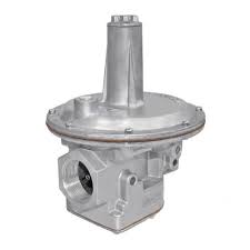
Safety is paramount in burner control design. Modern systems incorporate redundant safety devices, including flame detection (typically UV or infrared sensors), pressure relief mechanisms, and fuel isolation valves. The electrical interface components that connect these devices to the control system must meet specific reliability standards. For instance, control relays used in burner circuits require proven performance specifications and fail-safe characteristics to prevent dangerous system states.
Industrial facilities in Singapore operating under local safety regulations and best practices must ensure their burner control systems meet the requirements of Standards such as SS 1610 (Code of Practice for Safety in the Use of Oil-Fired Boiler Plants) and relevant safety interlocks. Understanding these regulatory requirements is essential before selecting control components.
Essential Control Components and Technical Specifications
Burner control systems integrate several critical component categories, each serving specific functions within the overall system architecture. Understanding the technical specifications and operational requirements of these components is essential for proper system design and installation.
Control Relays and Logic Elements: These components form the decision-making foundation of burner control systems. The CBM Relay TMG 740-3 63.55 represents a typical industrial-grade control relay used in burner management circuits. These relays provide electrical switching functions with certified safety ratings, enabling safe fuel valve control and interlock logic. Specifications such as switching capacity (typically 10-16 amperes for main contacts), operating voltage (usually 24VDC or 230VAC), and response time (milliseconds) directly impact system reliability.
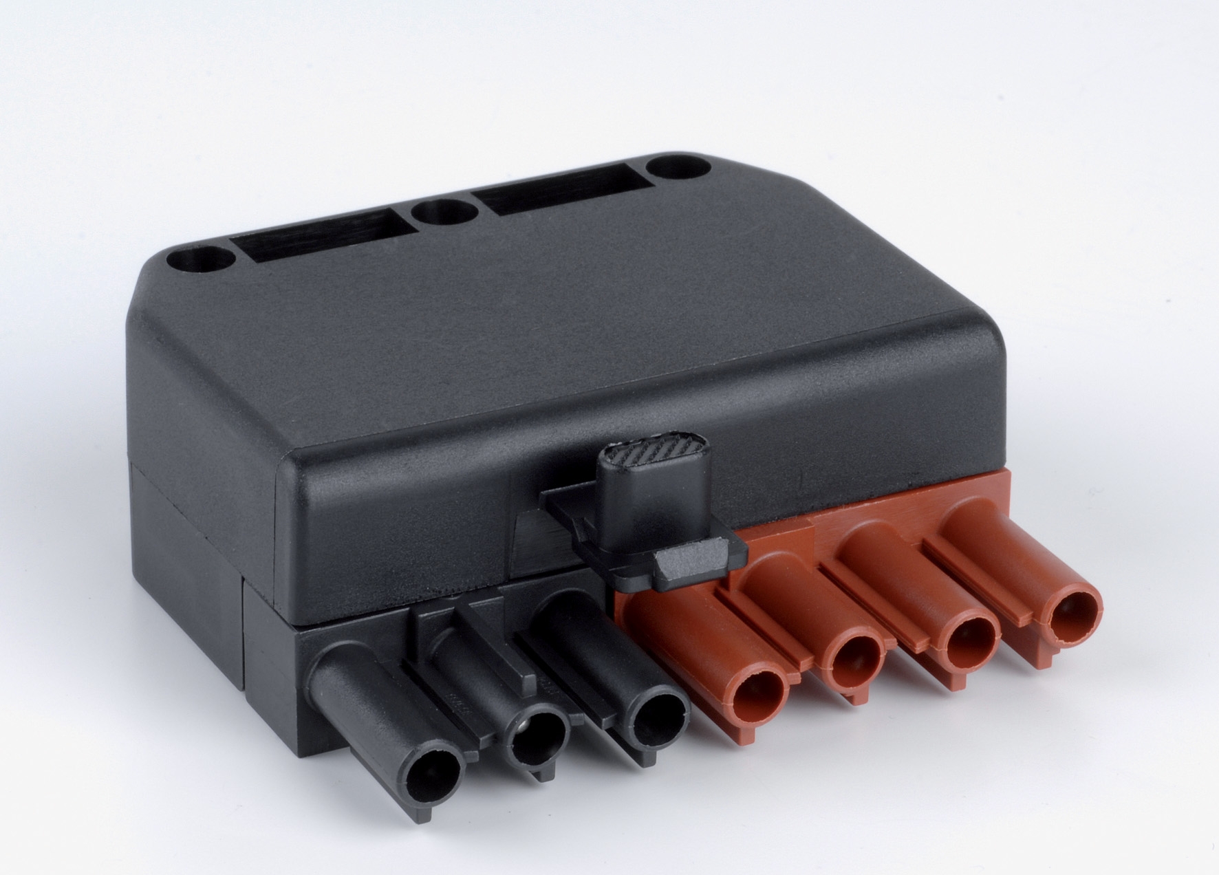
Electrical Interface Connectors: Reliable connections between control devices and field instruments are critical. The CBM 7 pole male connector provides standardized multi-pin connection capability for burner management systems. These connectors must withstand industrial environments, maintain contact integrity under thermal cycling, and resist corrosion—particularly important in Singapore's high-humidity coastal environment. Specifications include contact rating, environmental protection rating (IP rating), and mechanical durability for repeated mating cycles.
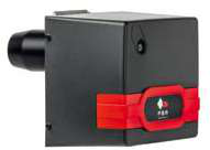
Burner Management Units: The FBR KN 1300/M TL EL represents a complete burner management system designed for industrial applications. These units integrate flame detection, fuel valve sequencing, air supply management, and safety interlocking into a single control module. Technical specifications include response times for flame detection (typically under 200 milliseconds), maximum switching frequency for modulating applications, and diagnostic output capabilities.
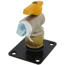
Mechanical Installation Components: Proper physical mounting of burner components requires specialized hardware. The FBR FLANGIA DISTANZIALE with 120mm height ensures correct spacing and alignment between burner components. These flanges must accommodate thermal expansion, maintain precise alignment tolerances (typically ±2mm), and provide secure fastening under operational vibration.
When selecting these components, technical data sheets from manufacturers provide essential information: electrical ratings, environmental operating ranges (typically -10°C to +60°C for control electronics in most industrial burners), response characteristics, and compatibility matrices with other system elements. Singapore distributors maintain these specifications in accessible formats to support equipment selection and troubleshooting.
Step-by-Step Installation Procedure for Burner Control Systems
Proper installation of burner control components follows a systematic sequence that ensures safety, functionality, and compliance with local standards:
Step 1: Pre-Installation Verification Before beginning installation, verify all components against the control system design specification. Confirm mechanical compatibility—check that flanges (such as the 120mm height spacing flanges) match your specific burner model. Verify electrical ratings match your facility's available voltage and current capacity. Document the current system configuration with photographs, as reference during reassembly.
Step 2: Isolate and Secure the Burner Isolate the burner from all energy sources: fuel supply (close isolation valves and bleed pressure lines), electrical supply (lockout/tagout procedures), and compressed air if applicable. Allow the system to cool to ambient temperature. Install appropriate safety signage indicating work in progress.
Step 3: Install Mechanical Components Install spacing flanges according to manufacturer specifications. For FGP series burners, ensure the 120mm height flanges align with mounting points. Use appropriate fasteners (typically stainless steel in tropical environments) and apply thread-locking compound. Torque fasteners to specification—typically 25-35 Nm for standard industrial connections, verified in your equipment manual.
Step 4: Install Electrical Connectors Connect the 7-pole CBM connectors, ensuring proper mating alignment. Inspect contact pins for corrosion or damage before connection. Apply dielectric grease to outdoor connections in Singapore's humid environment. Verify proper seating with a gentle pull test—properly seated connectors require deliberate effort to disconnect.
Step 5: Install Control Relays and Management Systems Mount the relay module or burner management unit in a protected location within your control cabinet. Ensure adequate ventilation around the unit (minimum 50mm clearance recommended). Connect according to wiring diagrams, maintaining clear cable routing and separation between power and signal circuits. Install the KN 1300/M TL EL management system according to its mounting bracket specifications.
Step 6: Verify System Configuration With electrical power applied (but burner isolated), verify relay operation through manual test buttons. Use a multimeter to confirm proper voltage at critical points. Run through the complete control sequence in manual mode before transitioning to automatic operation.
Step 7: Commission and Test With facility management approval, gradually restore operational conditions. Observe complete startup and shutdown sequences multiple times. Monitor flame detection response, fuel valve actuation timing, and safety shutdown performance. Document all test results for compliance records.
Component Selection Criteria and Best Practices
Selecting appropriate burner control components requires balancing multiple technical and operational considerations. Application Requirements: Define whether your burner operates in on-off mode or requires modulating control. Modulating burners demand components with faster response times and higher switching frequency capability than simple on-off systems. Determine your fuel type (natural gas, LPG, oil) as this affects control strategy—oil burners typically require more sophisticated atomization management than gas burners.
Environmental Conditions: Singapore's tropical climate presents specific challenges. Ambient temperatures frequently exceed 30°C, and humidity approaches 80-90% in coastal areas. Select components rated for extended temperature ranges and featuring enhanced corrosion protection. Stainless steel connectors (versus nickel-plated) provide superior durability in marine environments.
Safety and Compliance: Verify that selected components meet applicable Singapore standards and your facility's safety requirements. Control relays must be rated for safety-critical applications. Documentation from suppliers should clearly state compliance certifications.
Integration and Compatibility: Ensure all components operate on compatible voltage and communication protocols. The CBM Relay TMG 740-3 63.55 operates at specific voltage ratings—confirm your control system provides this voltage. Connector types must match across your system to prevent installation errors.
Maintenance and Support: Select components from established suppliers like 3G Electric that maintain local inventory and technical support. Longer lead times for replacement components can result in costly operational downtime. Favor components with established service networks in Singapore.
Maintenance and Troubleshooting Considerations
After installation, periodic maintenance ensures continued reliable operation. Test flame detection systems monthly by simulating flame loss and verifying system response. Inspect connectors semi-annually for corrosion, particularly in coastal facilities. Clean connector contacts with electrical contact cleaner and apply fresh dielectric grease. Monitor relay switching by audible inspection—a sluggish or intermittent click suggests contact wear requiring relay replacement.
Common troubleshooting scenarios include: intermittent flame detection (typically connector issues or sensor contamination), delayed fuel valve response (often relay contact wear or control signal problems), and nuisance safety shutdowns (frequently caused by sensor drift or electrical noise). Maintaining detailed operational logs helps identify patterns suggesting component degradation.
Component replacement should follow the same methodical approach as initial installation. Maintain compatibility with existing systems unless a complete system upgrade is planned. When replacing relays or management systems, document the serial numbers and installation dates for warranty and regulatory compliance.
Conclusion and Next Steps
Proper selection and installation of industrial burner control components ensures safe, efficient, and reliable combustion operations across Singapore's diverse industrial sector. The technical considerations covered in this guide—from understanding control system architecture through implementing step-by-step installation procedures—provide the foundation for successful equipment deployment and maintenance.
Industrial professionals facing burner control system projects should begin by thoroughly reviewing your current equipment specifications and defining precise operational and safety requirements. Consult with experienced equipment distributors in Singapore who understand local environmental conditions and regulatory requirements. 3G Electric's three decades of service to Singapore's industrial sector position them as a valuable resource for sourcing compatible components like the CBM 7-pole connectors, control relays, and burner management systems referenced throughout this guide.
Ready to upgrade or commission your burner control system? Contact 3G Electric today to discuss your specific application requirements. Our technical team can help you select the precise components needed and provide installation support to ensure your combustion system operates at peak efficiency and safety. Whether you need individual components like relays and connectors or complete burner management solutions, we maintain comprehensive inventory and expert technical guidance for industrial operations throughout Singapore.