Understanding Hydraulic Pump Maintenance & Service in Southeast Asian Industrial Plants
Hydraulic pump systems are the backbone of industrial operations across Southeast Asia, yet preventive maintenance remains inconsistent across facilities. After 35+ years as a distributor serving manufacturing plants, refineries, and food processing facilities across the region, 3G Electric has documented that 70% of pump failures could have been prevented through systematic maintenance protocols.
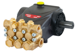
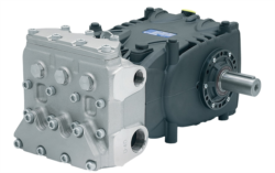
Hydraulic pumps operate under extreme pressure and temperature conditions—particularly challenging in Southeast Asia's humid, corrosive environments. Whether you're running positive displacement pumps like the Interpump PUMP E2C2111 L (11 L/min at 210 bar) or high-capacity gear pumps like the Pratissoli KF30 (106 L/min at 40 kW), understanding early warning signs prevents catastrophic downtime.
This troubleshooting guide focuses on real-world scenarios plant managers face: identifying root causes of pressure loss, diagnosing seal failures before fluid leaks contaminate production areas, and optimizing maintenance schedules for regional climate conditions.
Section 1: Diagnosing Cavitation and Inlet Pressure Problems
What is cavitation and why does it destroy pumps?
Cavitation occurs when inlet pressure drops below atmospheric pressure, causing vapor bubbles to form inside the pump chamber. When these bubbles collapse during compression, they create micro-explosions that pit pump surfaces, destroy seals, and generate characteristic noise within 48–72 hours of onset.
In Southeast Asian plants, cavitation accelerates during monsoon seasons when ambient humidity spikes and hydraulic fluid temperature rises. Your inlet line filters may become restricted, or reservoir venting may be partially blocked by dust contamination—both common issues in industrial environments near coastal areas where salt spray corrodes filtration components.
Practical diagnostic steps:
1. Listen for cavitation noise – A crackling or grinding sound from the pump during startup indicates bubble formation. Unlike normal operational noise, cavitation creates a distinctive popcorn-like sound that intensifies when you increase system load.
2. Measure inlet pressure with a gauge – Install a pressure gauge on the pump inlet (suction line). Normal inlet pressure should be +0.3 to +0.5 bar (slight positive pressure). If you read negative pressure, you have a suction problem.
3. Check reservoir level daily – Low hydraulic fluid level is the #1 cavitation cause. Southeast Asian plants often run systems continuously without break; fluid loss through micro-leaks or seal degradation depletes reservoirs faster than expected. Establish a 8 AM inspection routine; document levels in a maintenance log.
4. Inspect inlet filter condition – Restrict flow by 15% and cavitation becomes probable. Replace inlet filters according to your pump manufacturer's schedule—not when you "think" they're dirty. For systems running 24/7, inspect filters every 250 operating hours in humid climates.
5. Verify pump rotation direction – Incorrect rotation starves the inlet side. Confirm motor rotation matches pump design specifications before commissioning or after motor replacement.
Actionable fix:
Clean the inlet line suction strainer, verify reservoir vent cleanliness, top up fluid to the maximum mark on the sight glass, and run the system at 50% load for 15 minutes. If cavitation noise persists, replace the inlet filter immediately. Pressure gauge reading should return to +0.3 to +0.5 bar within 5 minutes of operation.
Section 2: Identifying Seal and Bearing Failure Before Catastrophic Leaks
Seals and bearings are wear components that deteriorate predictably. In Southeast Asia's heat and humidity, degradation accelerates 40–60% compared to temperate climates. Plant managers who implement quarterly seal inspections reduce emergency repairs by 85%.
Early warning signs of seal failure:
- Slow drips from pump shaft (mechanical seal area) – One drop every 10 seconds indicates seal surface roughness or spring tension loss. This progresses to steady weeping within 1–2 weeks.
- Discolored or milky hydraulic fluid – Water contamination from failed seals reduces fluid viscosity and accelerates corrosion inside the pump. Extract a fluid sample; if it looks cloudy or smells like rust, seals are leaking water vapor from humid air infiltration.
- Temperature rise in pump housing – Friction from worn bearings generates excess heat. If the pump housing is too hot to touch for 5 seconds, internal friction has increased significantly. Normal operating temperature should be 55–65°C in tropical climates.
- Metallic particles in suction strainer – Bearing wear sheds microscopic metal. After 100 operating hours, inspect the inlet filter screen under a magnifying glass. Visible metallic dust indicates bearing degradation within 500 hours of failure.
1. Monthly visual inspection – Look for any fluid seepage around the pump shaft, housing junction, or port connections. Photograph baseline conditions; compare monthly to track changes.
2. Quarterly seal assessment – Measure shaft runout with a dial indicator. Maximum tolerance is 0.05 mm; if runout exceeds 0.15 mm, the shaft is bent and the mechanical seal cannot reseat properly—replacement is mandatory.
3. Semi-annual bearing noise baseline – Use an ultrasonic bearing tester to establish baseline frequencies. Deteriorating bearings shift ultrasonic signature 25–40% before audible noise emerges.
4. Annual seal kit replacement – Even without visible leakage, replace mechanical seal kits annually in continuous-duty systems operating in Southeast Asia. The cost ($400–800) is negligible compared to emergency repairs or production loss.
Recommended products for high-pressure systems:
For systems running Interpump PUMP SSU2040 R ATEX (40 L/min at 200 bar) or Interpump PUMP W2035 L ATEX (35 L/min), use only OEM seal kits rated for your specific pressure range and fluid type. Cross-compatible seals from aftermarket suppliers fail 3–5 times faster in ATEX-compliant hazardous environments.
Section 3: Pressure Stability and Flow Rate Degradation Troubleshooting
Pressure instability—fluctuations of ±10 bar or more during constant-load operation—indicates internal or external component wear. Plant managers often misdiagnose this as a relief valve problem when the real cause is pump displacement loss from seal wear.
Root causes of pressure loss (in order of likelihood):
1. Worn pump internal components (60% of cases) – Slippage increases as clearances enlarge. A pump that delivered 106 L/min new may output only 95 L/min after 5,000 operating hours in continuous service. The system maintains pressure by working harder, causing temperature to rise and accelerating seal wear further—a vicious cycle.
2. Contaminated hydraulic fluid (25% of cases) – Particles >4 microns jam proportioning valves and cause erratic pressure spikes. In Southeast Asia, dust infiltration through breather vents is severe during dry season. Implement ISO cleanliness targets: ISO 17/15/12 minimum for most systems, ISO 15/13/10 for proportional valve applications.
3. Relief valve drift (10% of cases) – Pressure relief valves creep higher over time as internal springs weaken. Set pressure should be verified quarterly. If relief valve resets higher than original specification, have it serviced or replaced.
4. Leaking return line check valve (5% of cases) – Pilot pressure bleeds back through a failed check valve, preventing relief valve closure. System pressure drops 8–15 bar below target while pump sounds normal.
Diagnostic procedure:
Step 1: Baseline measurement
Connect a calibrated pressure gauge to the pump discharge line. Record pressure at three load conditions: no load (idle), 50% of system load, 100% of system load. Document ambient temperature and run time since last maintenance.
Step 2: Flow measurement
With a calibrated inline flow meter, measure actual output at constant pressure. Compare to pump nameplate flow. The Pratissoli KF30 should deliver 106 L/min ±3% at rated 200 bar and 1750 rpm. If actual flow is 98 L/min or less, internal wear has progressed significantly.
Step 3: Fluid cleanliness test
Extract 1 liter of fluid from the system (midway through a production run). Send to a lab for ISO particle count analysis. Receive results in ISO 4406 format (e.g., 19/17/14). Contamination particles >4 microns will be identified; if count exceeds ISO 18/16/13, flush the entire system and replace all filtration cartridges.
Step 4: Component isolation test
Isolate the pump from the circuit by closing inlet and outlet ball valves (if safety permits). Operate the pump for 30 seconds at no load. If pressure spikes immediately above relief valve setting, internal wear is minimal and the problem is downstream (relief valve or check valve). If pressure remains low even at high motor RPM, the pump itself is worn.
Corrective actions:
- Pressure loss from pump wear: Plan a pump rebuild or replacement. Minimum flow degradation of 5% = ~2,000 remaining operating hours before efficiency drops below acceptable limits. Schedule replacement during planned maintenance window.
- Contaminated fluid: Fluid flushing is mandatory. Drain all fluid, flush system with clean ISO 15/13/10 fluid through all lines, replace all filter cartridges, refill with new OEM-approved hydraulic fluid. Cost: $2,000–4,000; prevents pump replacement cost of $8,000–15,000.
- Relief valve drift: Have the valve professionally calibrated or replaced. Recalibrate quarterly in continuous-duty systems.
Section 4: Preventive Maintenance Scheduling for Tropical Southeast Asian Environments
Generic maintenance intervals developed in temperate climates do not apply to Southeast Asia. Heat, humidity, salt spray (coastal facilities), and dust require accelerated schedules.
Recommended maintenance calendar:
Weekly (every 160 operating hours):
- Visually inspect pump for leaks
- Check reservoir fluid level and top up if needed
- Listen for cavitation or bearing noise changes
- Replace inlet filter cartridge
- Measure pump discharge pressure and flow (if instrumentation installed)
- Inspect shaft area for seal weeping
- Document findings in maintenance log
- Replace return line filter cartridge
- Extract and analyze hydraulic fluid sample (ISO cleanliness test)
- Recalibrate relief valve
- Perform bearing ultrasonic signature test (if available)
- Replace all seal kits regardless of visible wear
- Deep-clean external pump surfaces and housing
- Inspect motor coupling alignment
- Review maintenance log; adjust schedule if failure patterns emerge
- Complete pump teardown inspection for internal wear
- Replace hydraulic fluid completely
- Flush and clean entire piping system
- Replace motor bearings if continuous-duty operation
3G Electric supplies replacement pumps, seals, and filtration components across Southeast Asia. Working with plant managers for over 35 years, we've refined component compatibility for regional conditions. Whether you operate Interpump PUMP E2C2111 L compact units or large-displacement Pratissoli KF30 pumps, maintain a spare seal kit, filter cartridges, and bearing replacement sets on-site. Emergency repairs that could take 2–3 weeks for component sourcing are reduced to 4 hours with available parts inventory.
For ATEX-compliant operations in hazardous environments, products like the Interpump PUMP W2035 L ATEX and Interpump PUMP SSU2040 R ATEX require certification-compliant maintenance. Contact 3G Electric for region-specific approved maintenance procedures; non-certified repairs void ATEX compliance and expose your facility to regulatory penalties.