Understanding Gas Valves & Regulation in HVAC Systems
Gas valves and regulation equipment form the critical control backbone of any modern HVAC heating system. Whether you're installing a new boiler system or retrofitting an existing installation, understanding how these components work together ensures safe, efficient operation and long equipment life. At 3G Electric, with over 35 years of experience distributing industrial equipment across Asia-Pacific, we've supported thousands of HVAC contractors through complex valve installations and commissioning processes.
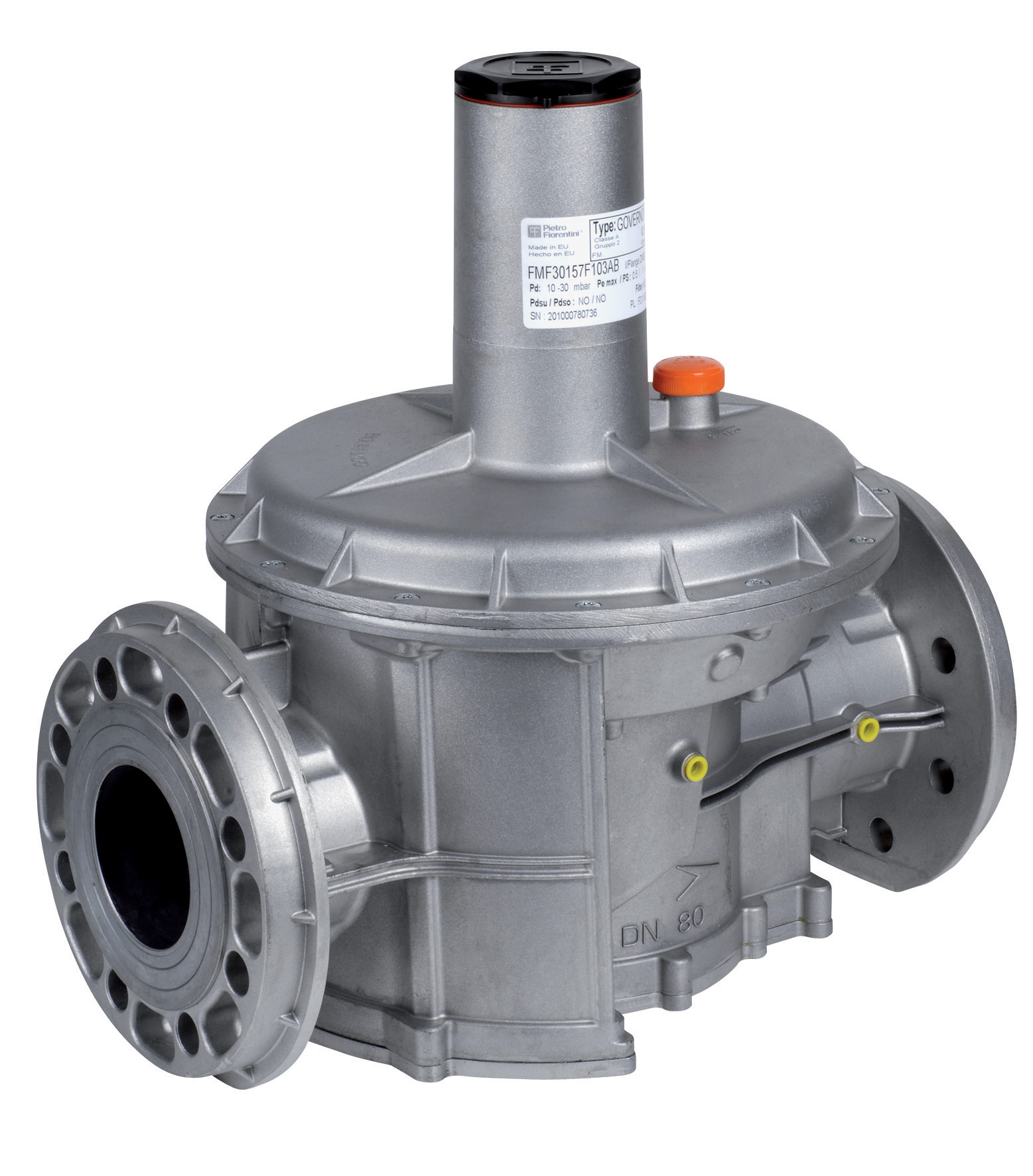
Gas valves serve multiple functions in HVAC systems: they control fuel supply to burners, maintain safe operating pressures, provide automatic shutoff during faults, and enable zone control for multi-area heating networks. Regulation equipment—including pressure regulators, safety shutoff valves, and flow control devices—ensures that gas reaches burners at precisely calibrated pressures and flow rates. In Singapore's high-humidity tropical environment, proper installation and commissioning becomes even more critical, as moisture and salt air can affect component performance if not properly sealed and protected.
For HVAC contractors, the installation phase determines whether a system will operate reliably for 10-15 years or experience premature failures. This guide walks you through the complete process from pre-installation planning through final commissioning and handover.
Pre-Installation Planning and Component Selection
Assessing Your System Requirements
Before purchasing any valves or regulators, conduct a thorough system audit:
- Gas type and supply pressure: Confirm whether you're working with natural gas (town gas in Singapore typically at 20 mbar) or LPG, and verify incoming supply pressure at the meter.
- Heating load and flow rates: Calculate required gas flow in m³/h at operating conditions. Most HVAC systems require flow rates between 2-8 m³/h depending on boiler capacity.
- Operating pressure requirements: Determine the pressure needed downstream of your regulator. Typical burner requirements range from 20-50 mbar for atmospheric burners, up to 100+ mbar for power burners.
- System configuration: Identify whether you need single-stage or two-stage regulation, and whether zone valves for area control are required.
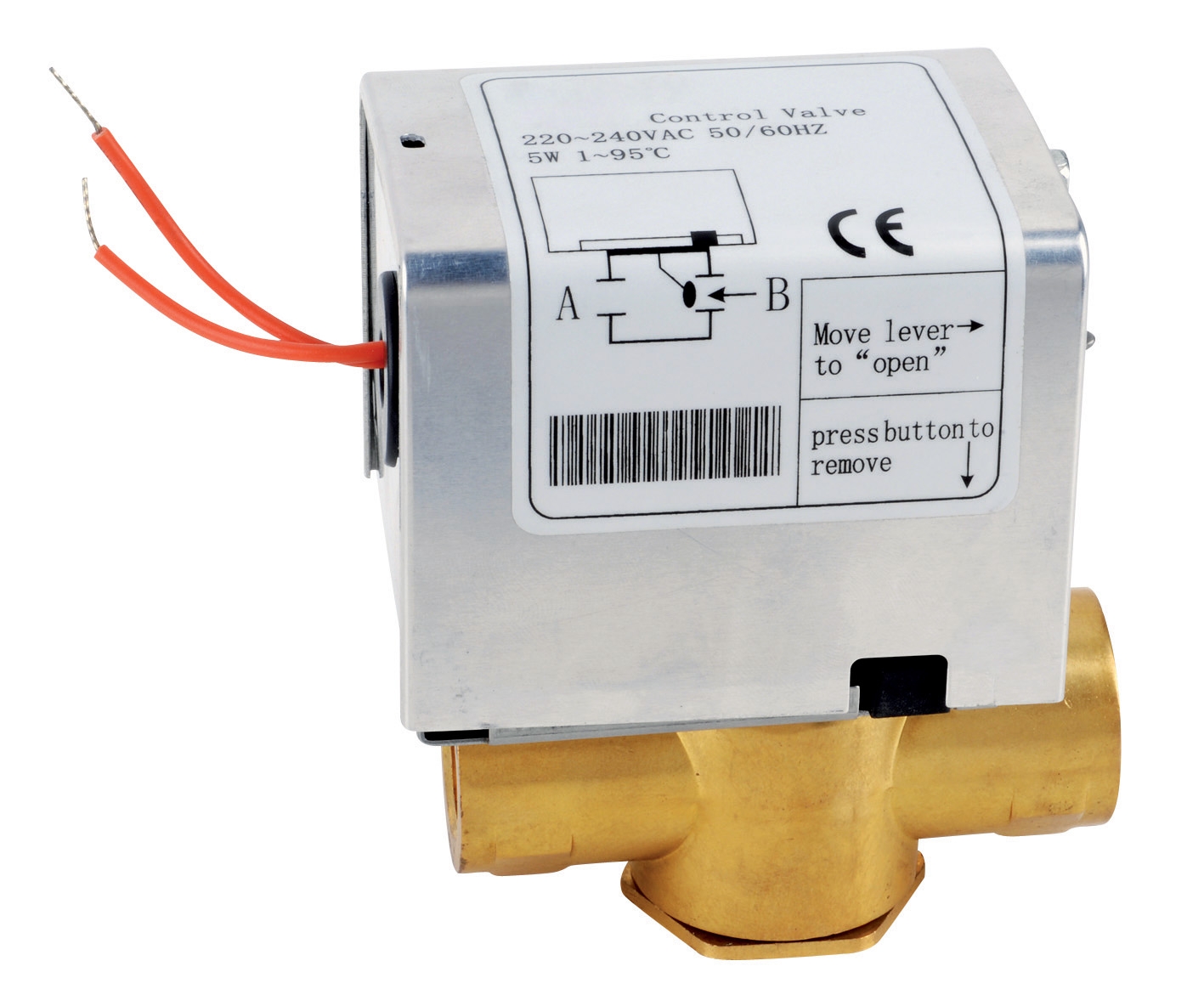
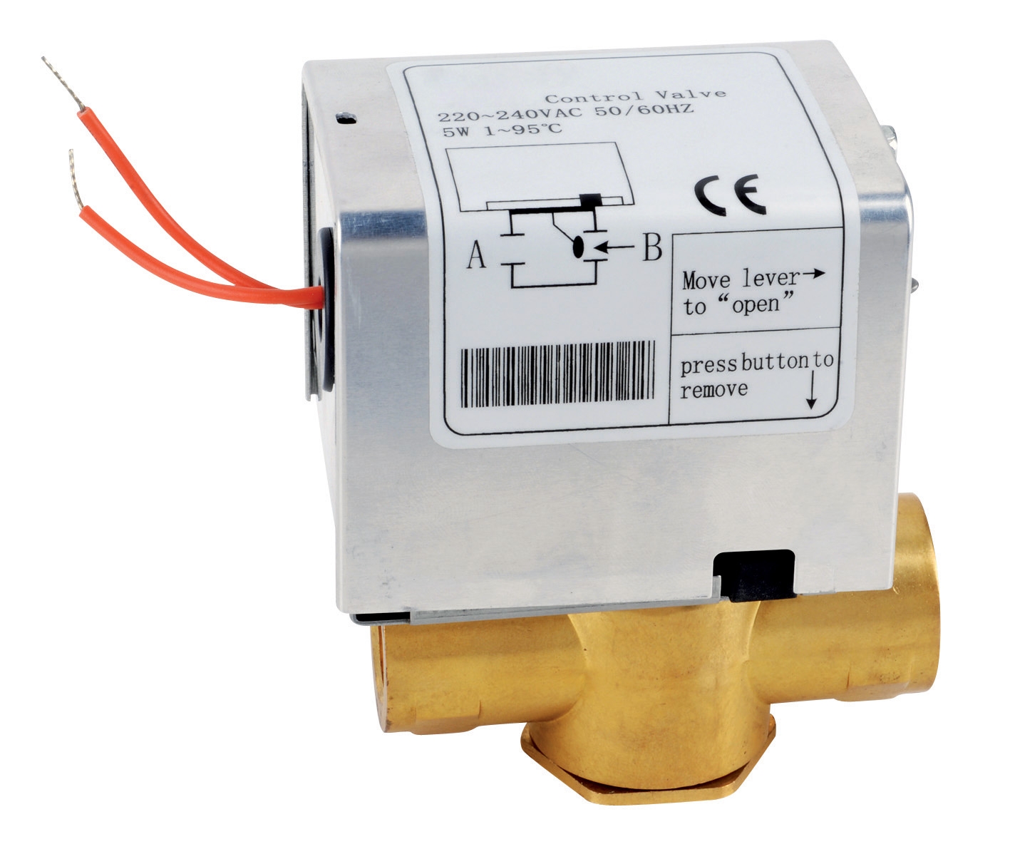
For multi-zone HVAC systems common in Singapore commercial buildings, consider the ELV 2-way zone valve 1" with auxiliary contact for controlling hot water distribution to different zones while maintaining proper gas pressure sequencing. The 1" connection size handles typical commercial boiler piping, while the auxiliary contact enables electrical interlocking with burner management systems.
Selecting Appropriate Valve Types
Three main valve categories appear in HVAC gas systems:
- Manual isolation valves: Brass ball valves with handle locks for safe shutdown during maintenance. Install one before and after your main regulator.
- Automatic safety shutoff valves: Solenoid-operated valves that cut gas supply on pilot flame loss or safety signal. These must meet Singapore's Safety of Pressure Equipment (SOPE) regulations.
- Modulating control valves: Proportional or solenoid valves that adjust flow based on demand signals from thermostats or building management systems.
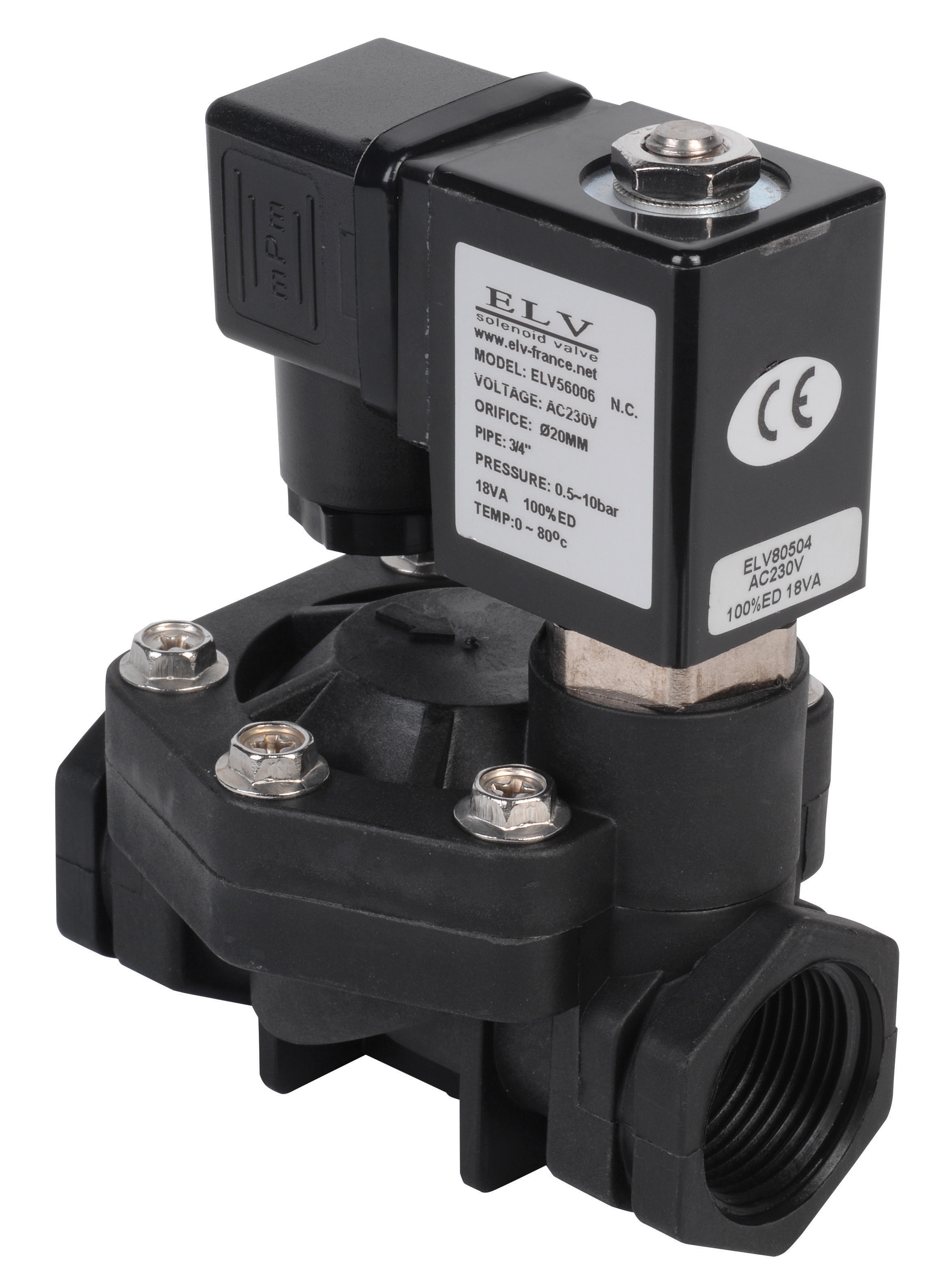
For simpler applications, the ELV Plastic solenoid valve D.3/4 NF 230V provides a cost-effective solution for automation and process control applications where pressures remain below 10 bar. However, confirm with manufacturers that plastic components are suitable for your specific gas type and local humidity conditions.
Installation Procedures and Pressure Testing
Pipe Preparation and Layout
Follow these critical steps before installing any valves:
1. Purge all new piping: Run nitrogen gas through copper or steel piping at 1.5 times operating pressure for 15 minutes minimum to remove dust, moisture, and debris. This prevents regulator blockage—a common failure mode in tropical climates.
2. Install sediment traps: Place a vertical tee with drain valve at the lowest point before your main regulator. Sand, pipe scale, and corrosion products accumulate here and must be drained weekly during commissioning, then monthly thereafter.
3. Slope piping appropriately: Maintain a slight downward slope (minimum 1:100) toward the regulator inlet to prevent water accumulation in the supply line. Singapore's humidity means condensation will form—proper slope is essential.
4. Support piping every 1.5 meters: Use copper pipe clamps with rubber insulation to isolate vibration from burner controls and minimize stress on valve connections.
Regulator and Valve Installation
When mounting your main pressure regulator:
- Install on a vertical or slightly inclined section of pipe (never horizontal or inverted)
- Ensure at least 150mm of clear space below the regulator vent for atmospheric discharge
- Mount the outlet pressure gauge on the downstream side within 300mm of the regulator
- Use PTFE thread seal tape (minimum 4 wraps) on all male pipe connections; do not use sealant compound, which can be drawn into valve seats
- Tighten fittings with two wrenches—one holding the valve body, one turning the fitting—to prevent internal damage
For zone control installations requiring multiple valves, the ELV 2-way zone valve 1/2" provides reliable modulation of hot water circuits. Position this valve horizontally with the solenoid coil pointing upward (or as manufacturer specifies) to prevent water pooling in the coil cavity.
Pressure Testing Protocol
Before any gas enters the system, conduct a complete pressure test:
1. First stage—air test: Close all isolation valves and apply 100 mbar compressed air to the system upstream of the main regulator. Listen for leaks at every fitting using soapy water. Mark any leaks for tightening.
2. Second stage—gas test: With all burner pilot lights extinguished and safety switches set to "test," open the gas supply slowly. Retest every fitting at 50 mbar with soapy water. Any bubbling indicates a leak that must be repaired before proceeding.
3. Pressure hold test: Close the downstream isolation valve and observe inlet pressure gauge for 10 minutes. No pressure drop indicates a sound system. Any drop suggests a regulator seat leak requiring regulator replacement.
4. Documentation: Record all test pressures, times, and any repairs in your commissioning log. Singapore's Building and Construction Authority (BCA) may require this documentation during inspections.
Commissioning, Calibration, and Safety Verification
Regulator Outlet Pressure Setting
Proper regulator calibration directly affects burner performance and safety:
1. Reference manufacturer specifications: Locate the gas boiler's burner pressure requirement from the equipment nameplate. For most atmospheric burners, this is 20-30 mbar; for power burners, 80-120 mbar.
2. Initial setting: Using a calibrated pressure gauge on the outlet side, slowly open the regulator adjustment screw (typically a spring-loaded screw on the regulator body) until outlet pressure reaches approximately 90% of target. Do not overshoots—regulators cannot reduce pressure quickly.
3. Load testing: Light the burner and increase the heating demand to maximum. Observe the outlet pressure gauge—it should remain within ±5% of your set point despite the increased flow demand. If pressure drops significantly under load, you may have an undersized regulator; contact your supplier.
4. Fine-tuning: Return to your target pressure and lock the adjustment screw with a lock nut if provided. Take a final reading and photograph the gauge for your records.
Solenoid Valve Testing
For solenoid-operated safety and modulating valves:
1. Manual operation test: Close manual isolation valves on both sides of the solenoid valve. Apply a small test gas bottle (1-2 bar) directly upstream. Energize the solenoid coil—you should hear a distinct click and feel pressure downstream. De-energize and confirm pressure bleeds away.
2. Leakage test: With gas applied and the solenoid de-energized, apply soapy water to the outlet. No bubbles should form over 5 minutes, indicating a tight shutoff.
3. Response time verification: For modulating valves like zone control applications, use your system's burner management controller to command valve modulation from 0-100%. Watch the outlet pressure gauge respond smoothly without chattering or hunting.
Pilot Light and Ignition System Verification
Before handover, ensure proper pilot light operation:
1. Pilot pressure check: With the main burner off and pilot light burning, measure pilot supply pressure (typically 10-15 mbar). Record this value.
2. Flame failure simulation: With the pilot burning, manually extinguish the flame (or use the burner's test mode). The main gas valve must shut off within 2 seconds. If it does not, the flame sensor is faulty—do not commission the system.
3. Ignition sequence timing: Observe a complete ignition sequence: pilot light delay, main valve opening, burner ignition, and flame stabilization. The entire sequence should take 5-10 seconds. Any hesitation or delayed ignition suggests regulator or valve issues.
Safety Interlock Commissioning
Test all safety interlocks before system handover:
- High-limit thermostat: Disable the thermostat call for heat; burner must not fire
- Low-pressure switch: Simulate a loss of gas supply by closing the main isolation valve; the safety valve must shut off flow within 2 seconds
- Air pressure switch (if applicable): Confirm the blower runs and pressurizes the combustion air chamber before the safety valve opens
- Vent damper operation: If installed, verify the damper opens when the burner fires and closes within 30 seconds after shutdown to prevent backdrafting
Document all test results on your commissioning report with timestamps and technician signatures. This documentation is essential for warranty claims and regulatory compliance in Singapore.
Ongoing Maintenance and Performance Optimization
Monthly Inspection Routine
Schedule regular maintenance visits to ensure sustained performance:
1. Sediment trap drainage: Open the drain valve at your inlet sediment trap for 30 seconds to expel accumulated debris. In Singapore's humid environment, this may collect water even if piping slopes correctly.
2. Pressure gauge reading: Record outlet pressure at idle and full load. Compare to your commissioning baseline. A pressure drop of more than 10% suggests regulator diaphragm degradation or a valve leak.
3. Visual inspection: Check for corrosion on copper piping, water beading on valve bodies (indicating condensation), or discoloration of solenoid coil insulation.
4. Flame observation: During heating operation, observe the burner flame color and shape. A flame that's too yellow (instead of blue-white), lifts off the burner, or rolls across the burner face indicates pressure or valve issues requiring immediate adjustment.
Annual Service Protocol
At minimum annually, perform these preventive tasks:
- Regulator internal inspection: For critical systems, have a qualified technician bench-test the main regulator to verify diaphragm integrity and seat condition
- Solenoid valve coil resistance check: Using a multimeter, measure coil resistance (typically 1-5 kilohms for 230V coils). If resistance is open circuit or extremely low, replace the coil
- Filter element replacement: If your system includes a gas filter/regulator combination, replace the disposable filter element annually to maintain proper regulation accuracy
- Pressure test repeat: Every 2-3 years, conduct a full pressure test as described in the commissioning section to identify slow leaks before they become safety issues
If your newly commissioned system exhibits these problems, follow these diagnostic steps:
Issue: Burner hunting (pressure oscillating ±20 mbar)
- Cause: Usually undersized outlet piping or demand-side restriction
- Solution: Trace the piping from regulator to valve; look for kinked copper or partially closed valves. Increase piping diameter if velocity exceeds 4 m/s.
- Cause: Insufficient pilot pressure or water contamination in gas line
- Solution: Verify pilot pressure is 12-15 mbar. Drain the sediment trap completely and retest. If problem persists, flush the entire system with dry nitrogen.
- Cause: Solenoid coil winding failure or control signal loss
- Solution: Check coil resistance with multimeter; if open circuit, replace coil. Verify 24V signal reaches the valve using a voltmeter across the coil terminals during thermostat call-for-heat.
- Cause: Regulator vent port blocked or relief valve stuck open
- Solution: Check that regulator vent is not plugged with tape or paint. If vent is clear, the relief valve seat may be contaminated—flush with nitrogen and retest.
With over 35 years of equipment distribution experience, 3G Electric has supported contractors through thousands of HVAC installations. When you encounter complex commissioning challenges, we can help source replacement components quickly and provide technical guidance based on real-world field experience.
Conclusion
Proper installation and commissioning of gas valves and regulation systems is not optional—it's the foundation of a safe, reliable HVAC installation that will serve your customers for a decade or more. By following this systematic approach, you'll avoid costly callbacks, reduce warranty claims, and build a reputation for quality workmanship that commands premium pricing in Singapore's competitive HVAC market.
The investment in proper pressure testing equipment, calibrated gauges, and thorough documentation pays for itself after just a few avoided failure callbacks. Pair these procedures with quality components sourced from reliable distributors, and you'll have a proven formula for HVAC system success across Singapore's challenging tropical environment.