Introduction to Gas Valves & Regulation
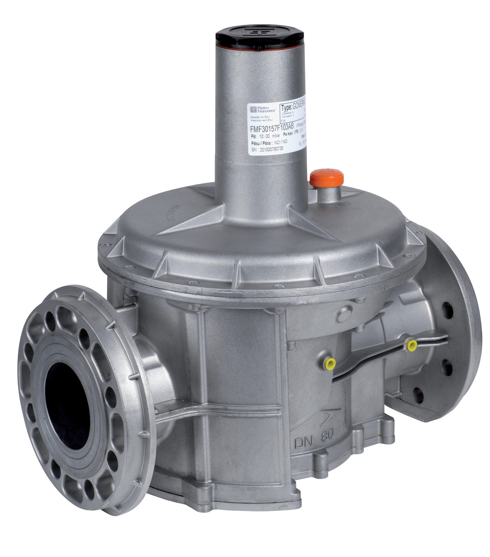
Gas valves and regulation systems form the critical backbone of industrial process control, combustion safety, and fluid management across Singapore's manufacturing, petrochemical, and HVAC sectors. Unlike simple on-off components, modern gas regulation requires precision calibration, proper installation sequencing, and continuous performance monitoring to maintain operational efficiency and regulatory compliance.
With over 35 years of experience as an industrial equipment distributor, 3G Electric understands that proper installation and calibration of gas valves directly impacts system reliability, energy efficiency, and safety compliance. This comprehensive guide provides industrial professionals—including maintenance engineers, plant managers, and commissioning specialists—with actionable procedures for installing, calibrating, and optimizing gas valve regulation systems in diverse Singapore industrial applications.
The difference between adequate and excellent gas valve performance often lies in calibration precision and installation methodology. This guide addresses those critical technical factors.
Section 1: Pre-Installation Assessment and Equipment Selection
Evaluating Your System Requirements
Before installation begins, conduct a comprehensive system assessment to determine exact gas valve specifications. This assessment should document:
Pressure Requirements: Measure your system's operating pressure range, maximum allowable working pressure (MAWP), and pressure fluctuation patterns. Singapore's industrial facilities often operate between 2-10 bar for low-pressure applications and up to 70+ bar for high-pressure systems. Use a certified pressure gauge to establish baseline readings across your existing system.
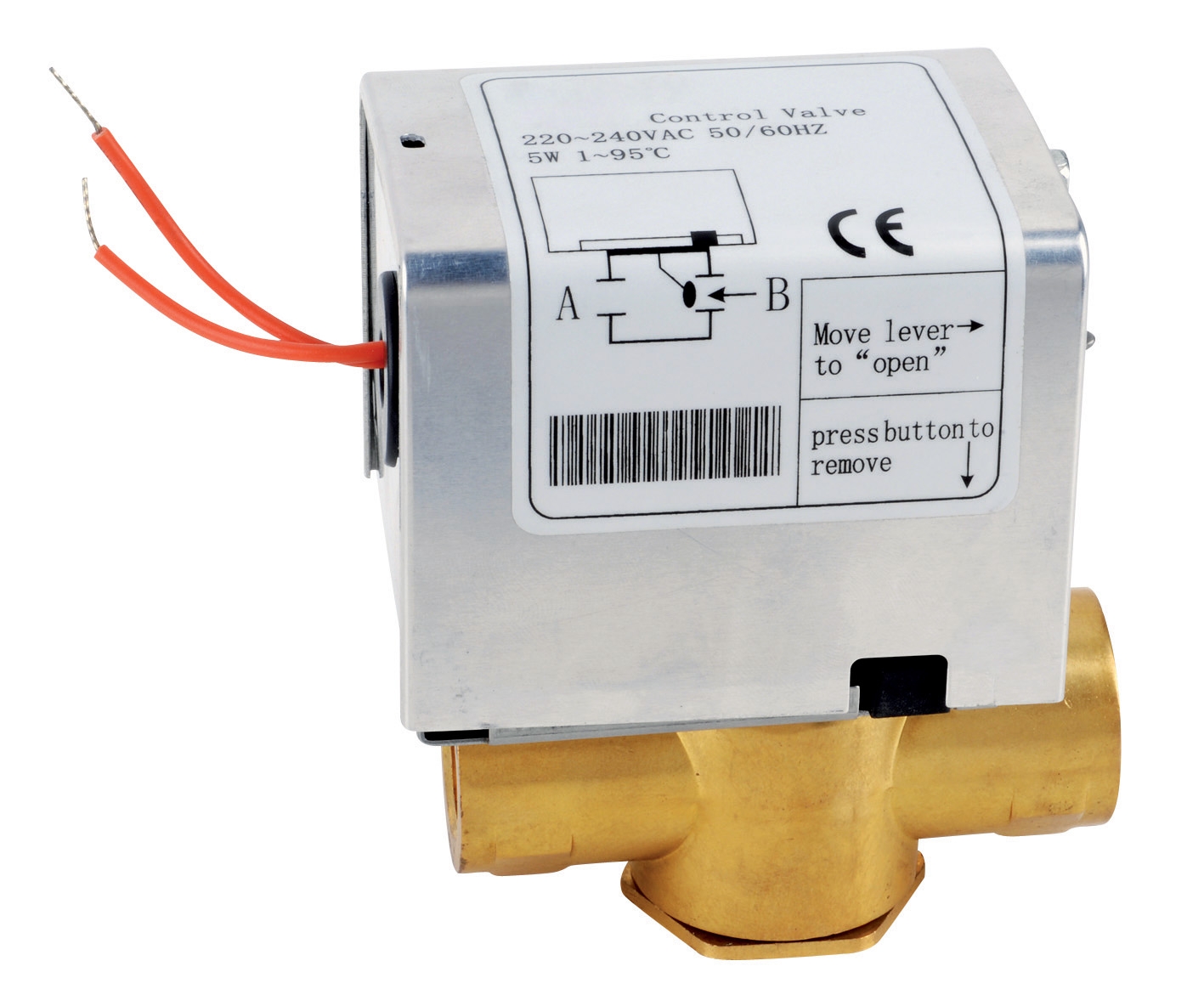
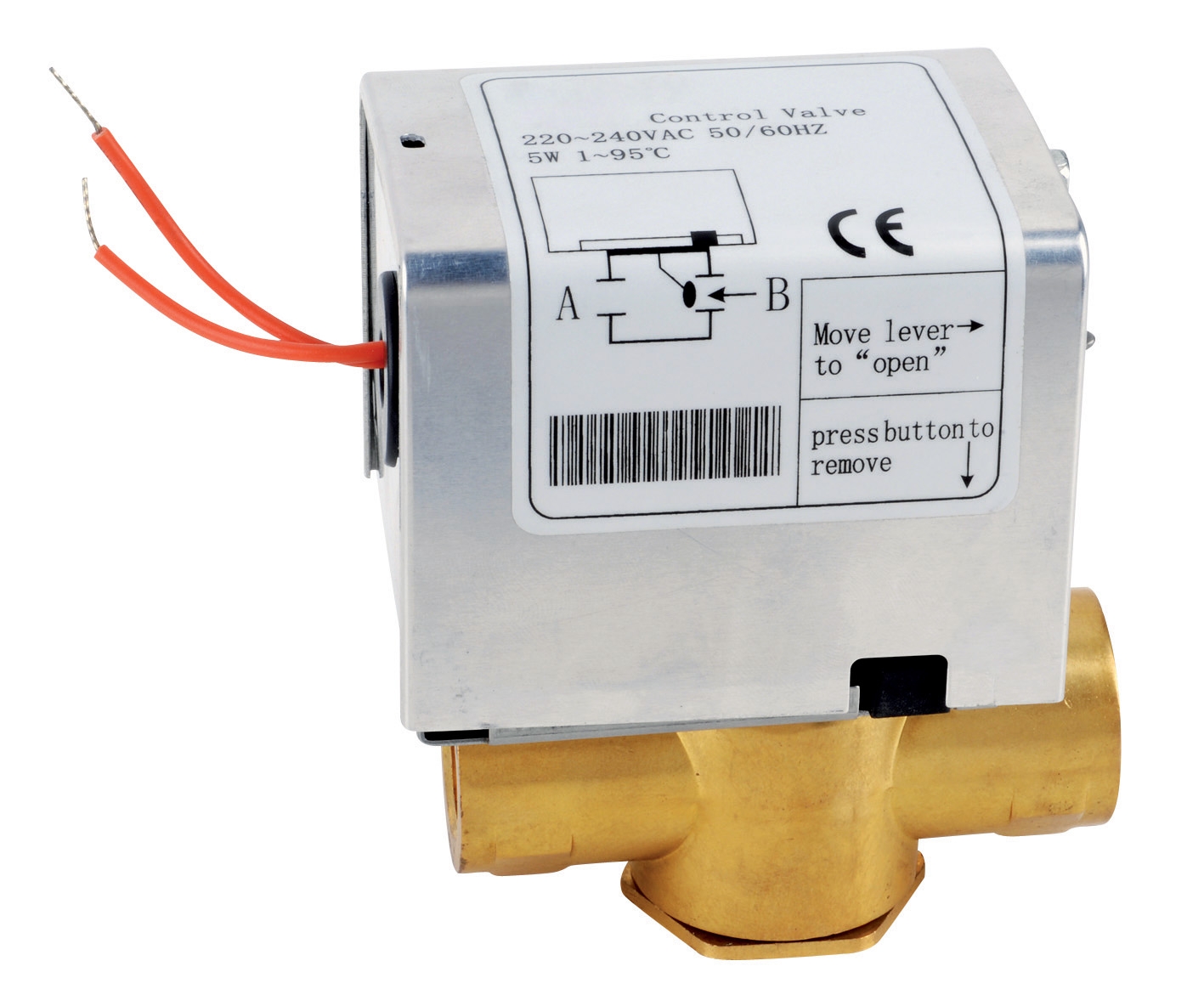
Flow Rate Specifications: Calculate required volumetric flow rates (m³/h or L/min) at standard operating conditions. Cross-reference this against valve Kv values—the flow coefficient indicating how much fluid passes through at a given pressure drop. For example, the ELV 2-way zone valve with 1" connection delivers 6.9 m³/h at maximum pressure, making it suitable for larger HVAC distribution systems.
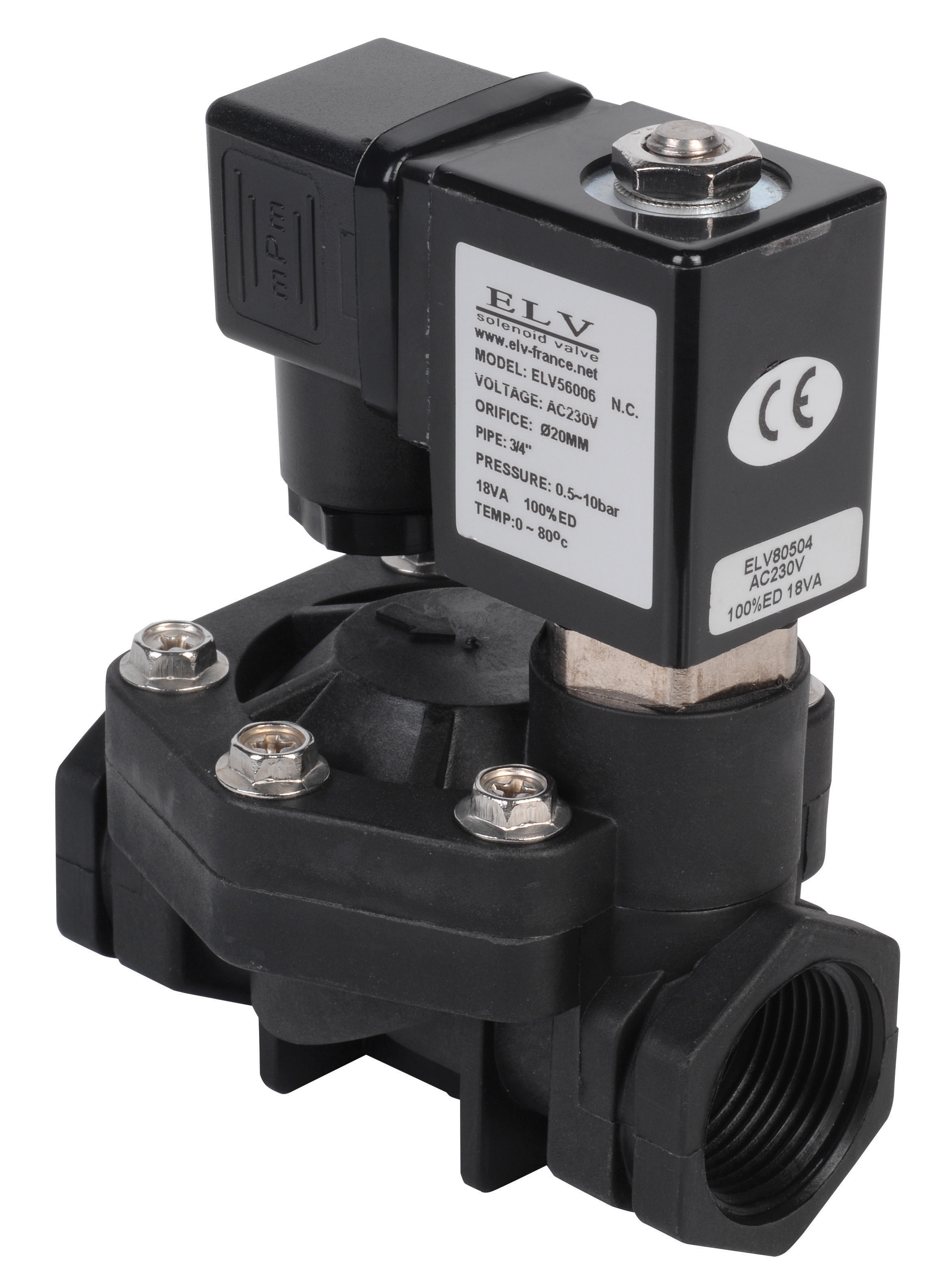
Fluid Compatibility: Identify the exact media—natural gas, compressed air, liquefied petroleum gas (LPG), water, or specialized fluids like synthetic oils. Temperature ranges and chemical composition affect material selection. The ELV plastic solenoid valve handles compressed air, water, and light oils at 0.5-10 bar pressure, demonstrating material versatility for multiple fluid types.
Connection Port Sizes: Document existing piping diameters (DN15, DN25, DN40, etc.) and thread types (NPT, BSPP, or ISO). Port size mismatches create installation complexity and pressure drop issues. Measure existing connections before ordering replacement valves.
Environmental Conditions: Record ambient temperature ranges, humidity levels (critical in Singapore's tropical climate), vibration levels, and potential corrosive atmospheres. Industrial facilities near coastal areas or chemical plants may require stainless steel valve bodies instead of standard materials.
Selecting Appropriate Valve Types
Different applications demand different valve architectures:
Solenoid Valves for Automation: When your system requires remote switching or integration with PLC/automation systems, solenoid valves provide reliable on-off control. The ELV 2-way zone valve (DN15) operates at 220V ±10%, 50/60Hz with fast response times under 7 seconds—ideal for Singapore's standard electrical supply.
Proportional and Modulating Valves: For applications requiring continuous pressure and flow adjustment (not just on-off), proportional valves provide graduated control. These valves accept electrical signals (0-10V or 4-20mA) for fine-tuned regulation.
High-Pressure Systems: For specialized applications like industrial cleaning or high-pressure hydraulics, ensure your valve handles sustained pressure loads. The Pratissoli SRS65 pump valve delivers precise flow control at 170 bar maximum pressure for demanding industrial fluid systems.
Zone Valves for HVAC: Heating and cooling distribution systems benefit from multi-zone control. The ELV 2-way zone valve with auxiliary contact enables individual zone management while providing feedback signals to building management systems.
Section 2: Installation Procedures and System Piping
Pre-Installation Preparations
Proper preparation prevents costly field modifications and system failures:
Isolate and Depressurize: Before any installation work, isolate the section of piping where the valve will be installed using block-and-bleed isolation valves. Depressurize the system completely and verify zero pressure using certified gauges. This is non-negotiable for worker safety and system integrity.
Clean Piping Systems: High-pressure gas valve failures often result from particulate contamination—iron oxide, welding slag, or manufacturing debris circulating through newly commissioned piping. Flush all new piping sections with compressed air at 5-10 bar for at least 15-20 minutes, directing exhaust into a safe area. For water systems, flush with clean water until discharge runs clear (typically 30-60 minutes for new installations).
Inspect Connection Threads: Check all NPT, BSPP, or ISO threads for damage, corrosion, or contamination. Use a thread inspection gauge if available. Damaged threads require replacement pipe sections—attempting installation on compromised threads causes leaks and safety hazards.
Prepare Installation Area: Ensure adequate working space (minimum 300mm clearance around valve connections), proper lighting, and appropriate tools. Have absorbent material available for potential fluid spillage, particularly important in Singapore's strict environmental compliance framework.
Valve Installation Sequencing
Step 1: Mount Manifold or Block Valve
If using manifold-mounted valves, install the manifold base on securely mounted brackets. Ensure manifold surface is clean and free from dust. Tighten mounting bolts in a crisscross pattern to 15-20 Nm (typical specification), not sequentially, to ensure even pressure distribution across sealing surfaces.
Step 2: Apply Thread Sealant
Apply PTFE tape (Teflon tape) to NPT male threads—wrap 3-4 layers clockwise, stretching tape gently to prevent bunching at the thread root. For BSPP threads, use anaerobic thread sealant (Loctite 572 equivalent), applying a thin bead around the thread. Do not use both methods simultaneously; they create sealing redundancy that may cause fitting distortion.
Step 3: Hand-Tighten First
Screw the valve fitting by hand to seated position without forcing. This allows visual confirmation of thread engagement and prevents cross-threading, a common installation error in time-pressured field situations.
Step 4: Use Dynamic Wrench Torque
Apply wrench torque gradually using a calibrated wrench, not impact wrenches which create uneven sealing loads. Target torque values:
- Ø8-10mm (5/16") fittings: 10-15 Nm
- Ø12-14mm (1/2") fittings: 20-25 Nm
- Ø16-18mm (3/4") fittings: 30-35 Nm
- Ø20-22mm (1") fittings: 40-50 Nm
When you feel resistance increase noticeably (typically 0.5-1.0 additional rotation after initial seating), stop turning. Over-tightening strips threads and damages internal valve seals.
Step 5: Install Inlet and Outlet Piping
Connect inlet piping first, leaving outlet side accessible for initial flushing or testing. Use flexible piping sections (internal diameter appropriate to flow requirements) rather than rigid pipes when possible, reducing vibration transmission and accommodating minor thermal expansion.
Step 6: Install Pressure Gauges and Test Points
Mount pressure test ports (0-10 bar or 0-16 bar gauges depending on system pressure) upstream and downstream of the valve. These enable real-time pressure drop verification during commissioning and ongoing diagnostics. Use needle-valve isolation taps at test ports for safety.
Section 3: Calibration and Performance Optimization
Initial System Pressurization and Leak Testing
Pressurize Gradually: After installation, introduce system pressure incrementally. For gas systems, increase by 0.5 bar intervals, pausing 2-3 minutes at each step to allow thermal stabilization. For water or liquid systems, increase by 1.0 bar intervals. Monitor for audible leaks (hissing at connections) or visible seepage around fittings.
Apply Leak Detection Solution: Mix bubble solution (liquid soap and water) and apply to all valve connection points. Visible bubbles indicate leaks requiring fitting re-tightening or resealing. Do not proceed to full system pressure with active leaks.
Establish Baseline Pressure Drop: Record pressure readings at inlet and outlet ports at nominal operating flow. The pressure differential (ΔP) should match the valve's Kv specification within ±5%. Excessive pressure drop indicates undersized valves or restricted inlet piping.
Fine-Tuning Regulator Settings
Once the system achieves stable baseline pressure without leaks, adjust regulator settings to match process requirements:
Locate the Regulator Adjustment Screw: Most industrial gas regulators feature a hex-head screw on the regulator bonnet (top or side, depending on manufacturer design). This screw directly adjusts spring tension controlling outlet pressure.
Establish Setpoint: Turn the adjustment screw clockwise to increase outlet pressure or counterclockwise to decrease pressure. Make quarter-turn (90°) adjustments only, pausing 30-60 seconds between adjustments to allow pressure stabilization. Small adjustments prevent overshoot.
Verify Against Downstream Load: The regulator outlet pressure should stabilize 0.2-0.5 bar above the maximum downstream system pressure requirement. This safety margin ensures consistent pressure delivery even when downstream components add resistance.
Record Setpoint Position: Use a permanent marker to mark the final screw position on the regulator bonnet. This reference point allows rapid return to correct settings if future adjustments become necessary, essential during emergency restart situations.
Advanced Optimization: Response Time and Stability Testing
Dynamic Response Test: For applications where fast pressure response matters (automated burner control, PLC-integrated systems), perform dynamic response testing. Abruptly open a downstream load valve (like a pilot gas burner) while monitoring inlet and outlet pressure gauges. Record the time between load application and stable outlet pressure achievement. Most quality regulators achieve stable response within 2-3 seconds for pressure load changes.
Stability Under Fluctuating Load: Introduce variable downstream flow while monitoring outlet pressure. Quality regulators maintain ±0.1 bar pressure variation across flow ranges. If pressure oscillates beyond ±0.2 bar, the regulator likely requires adjustments or cleaning of internal ported passages.
Hysteresis Measurement: Slowly increase then decrease downstream flow while recording outlet pressure. Properly calibrated regulators show minimal difference ("hysteresis") between rising and falling pressure curves—typically less than 0.05 bar for precision instruments.
Integration with Control Systems
For solenoid valves like the ELV plastic solenoid valve operating at 230V 22 VA, verify proper electrical integration:
Coil Voltage Verification: Measure actual supply voltage at the valve coil terminals. Singapore's standard 230V supply typically ranges ±10%. Operating outside this window (below 207V or above 253V) reduces solenoid force and causes intermittent switching failures.
Switching Response Time: After electrical connection, command the solenoid from its control system and measure response time using a pressure gauge or flow meter. Response times should be consistent and predictable for proper sequence control.
Load Testing: Run the integrated system under actual operating load for minimum 4 hours continuous operation, monitoring all gauge readings and control system feedback. This reveals latent issues with pressure surges, electrical noise, or thermal drift that static testing doesn't expose.
Section 4: Maintenance, Monitoring, and Long-Term Performance
Establishing Preventive Maintenance Routines
Weekly Visual Inspections: Check for external leakage at all connections, corrosion on valve bodies, and proper gauge operation. Leaking connections typically show mineral deposits (white residue on gas systems, rust-colored stains on iron-rich water systems).
Monthly Pressure Trending: Record inlet, outlet, and differential pressures at the same time each month. Plot these values to identify gradual drift. Rising outlet pressure with stable inlet pressure indicates downstream restriction (clogged filters or partially blocked outlets). Rising inlet pressure indicates supply-side restrictions.
Quarterly Response Time Validation: Re-test dynamic response times quarterly for critical applications. Degrading response times indicate internal valve wear, spool stiction, or solenoid weakening—all trigger points for preventive replacement before catastrophic failure.
Annual Professional Inspection: Engage qualified service technicians annually for comprehensive valve inspection including internal component examination, seal condition assessment, and complete system performance testing. This professional assessment catches issues invisible to routine visual inspection.
Troubleshooting Common Performance Degradation
Pressure Won't Hold at Setpoint: If regulator outlet pressure drifts up or down slowly after adjustment, debris likely lodges in the main valve seat. Isolate the regulator, depressurize, and locate the manual drain plug (typically a small hex fitting). Open the drain briefly to purge trapped particulates. Repeat pressurization and setpoint adjustment. For persistent drift, the valve likely requires internal service or replacement.
Erratic Pressure Oscillation: Oscillating outlet pressure while downstream load remains constant indicates regulator instability—often caused by undersized inlet piping, excessive inlet pressure above regulator rating, or worn internal springs. Verify inlet piping diameter matches manufacturer recommendations (typically one size larger than outlet). If oscillation persists, replace the regulator.
Solenoid Valve Won't Switch: Verify coil voltage first (should read within ±10% of rated voltage). If voltage is correct, measure coil electrical resistance (typically 900-1400 ohms for 230V coils). Open coil resistance indicates broken winding; zero resistance indicates shorted winding. Either condition requires coil or complete valve replacement. If electrical verification passes, debris likely obstructs the solenoid plunger—attempt cleaning by isolating and depressurizing the valve, then briefly opening and closing the solenoid multiple times to dislodge particles.
Documentation and System Records
Maintain comprehensive records for each gas valve and regulation system:
Installation Log: Document installation date, installer name, torque specifications applied, initial pressurization sequence, and all baseline pressure/flow readings.
Calibration Certificate: Record all adjustments made during commissioning, final setpoint values, and response time measurements.
Monthly Trend Log: Maintain spreadsheet with dated pressure readings, flow rates, and any maintenance actions taken.
Parts and Service History: Document all replacements, repairs, or professional service visits with dates, replaced components, and performance changes post-service.
These records provide invaluable diagnostic history if problems develop and demonstrate regulatory compliance for Singapore's industrial safety audits.
Conclusion
Successful gas valve installation and regulation optimization requires systematic attention to pre-installation assessment, precise installation methodology, careful calibration procedures, and disciplined ongoing maintenance. As Singapore's industrial sector increasingly demands higher reliability and energy efficiency, professional-grade installation and optimization of gas regulation systems directly impacts operational performance and regulatory standing.
3G Electric's 35+ years of experience in industrial equipment distribution has demonstrated that system failures rarely result from component defects—they overwhelmingly stem from installation shortcuts, inadequate commissioning procedures, or deferred maintenance. By implementing the installation procedures, calibration protocols, and maintenance routines outlined in this guide, Singapore's industrial professionals can achieve consistent, reliable gas valve performance and significantly extend component lifecycle.