Flame Detection Technology in Industrial Burner Controls: Infrared vs. Photo-Resistive Sensors
Flame detection represents a critical safety layer in automated burner control systems across global industrial applications—from catering facilities and heating plants to power generation and chemical processing. The choice between infrared sensors and photo-resistive detection technologies directly impacts system reliability, false-alarm rates, and maintenance overhead. This technical explainer examines the engineering principles, performance characteristics, and selection criteria for these two dominant flame monitoring approaches, enabling procurement and purchase engineers to specify the most appropriate technology for their operational context.
Core Principles: How Flame Detection Works in Burner Safety Systems
Flame detection in industrial burner controls operates on a fundamental principle: converting the optical signature of a flame into an electrical signal that a control device can interpret and act upon. Unlike manual visual inspection, automated flame sensing provides sub-second response times and eliminates operator bias from the safety loop.
Two optical detection technologies dominate industrial applications: infrared (IR) spectral sensing and photo-resistive cell technology. Both leverage the fact that combustion flames emit electromagnetic radiation across distinct wavelength bands. The critical difference lies in how they isolate and respond to that radiation.
Infrared sensors detect radiation in the 800–1100 nanometer spectral range (near-infrared), with peak sensitivity around 950 nm when equipped with daylight filters. This wavelength band corresponds to the natural emission spectrum of fuel flames—particularly the characteristic infrared output from blue-flame oil and gas combustion. Photo-resistive cells, by contrast, respond across a broader visible and near-visible spectrum, with sensitivity that varies by cell material and design.
The safety architecture surrounding flame detection integrates these sensors into a larger control loop: the sensor output feeds into a burner safety relay or control module, which interprets signal strength and frequency to confirm stable flame presence. If the signal falls below a programmed threshold—or extinguishes entirely—the control device triggers a safe shutdown sequence, cutting fuel supply and energizing alarms. This architecture ensures that loss of flame is detected and acted upon faster than manual intervention could achieve.
Technical Specifications and Real-World Performance Comparison
Understanding the specific performance envelope of each technology is essential for proper system selection.
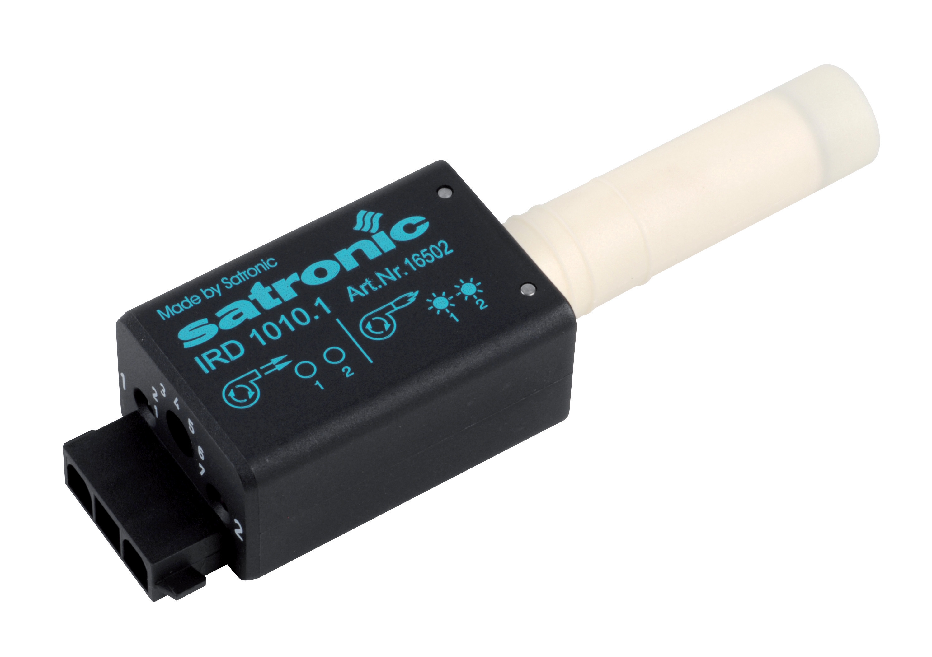
Infrared Flame Detection: The CBM IRD 1010 blue cell exemplifies modern infrared sensor design. Specified with a nominal supply voltage of 220–240 V (±15% to +10%), this detector operates across a frequency range of 15–250 Hz at −12 dB, accommodating the natural flicker rates of real combustion flames. The 800–1100 nm spectral window, narrowed to 950 nm with integrated daylight filtering, provides excellent immunity to ambient light interference. The IP 41 protection rating indicates sealed housing against dust ingress while remaining accessible for field installation—critical for burner room environments where combustion byproducts, dust, and moisture are present. Mounting flexibility (any orientation) allows integration into diverse burner geometries and enclosure designs.
The infrared approach offers superior discrimination between flame and background radiation. Because ambient daylight and incandescent lamp radiation peak in the visible and lower-infrared regions, an IR sensor tuned to 950 nm naturally rejects these false-alarm sources. This spectral selectivity makes infrared sensors particularly valuable in burner installations where spurious ignition sources or stray light could otherwise trigger nuisance shutdowns.
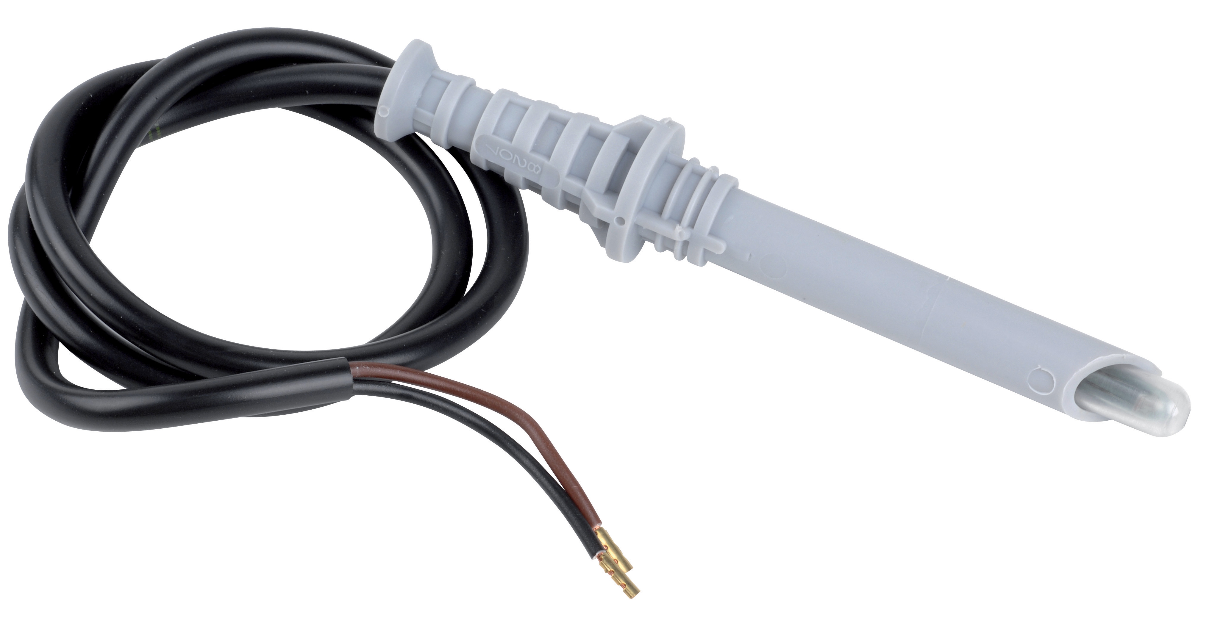
Photo-Resistive Flame Detection: The CBM Cell 8207, a photo-resistive sensor, operates on a fundamentally different principle. Rather than detecting specific infrared wavelengths, it responds to changes in visible light intensity via a variable resistance element. These cells require amplification electronics and impose a strict maximum operating temperature limit of 100°C—a critical constraint in close-proximity burner applications where radiant heat is significant. Photo-resistive cells exhibit broader spectral sensitivity, which provides robustness in detecting diverse flame colors (blue, yellow, orange) but also increases susceptibility to ambient light and electrical noise.
Historically, photo-resistive cells dominated burner control because of their simplicity and cost. However, they require more sophisticated filtering in the control electronics to distinguish true flame signal from background radiation, and their temperature sensitivity necessitates thermal management or protective mounting. The 100°C limit means installation must account for flame-radiated heat; mounting arms, optical ports, and wiring insulation must be selected with thermal headroom.
Integration into control architecture differs between the two: infrared sensors typically feed directly into a comparator or signal processor within a safety relay (such as oil burner controls), whereas photo-resistive cells historically required dedicated amplifier modules and more complex signal conditioning.
Real-World Application Scenarios and System Integration
The choice between infrared and photo-resistive detection manifests in real operational differences.
Oil and Biomass Burner Systems: In oil-fired heating and boiler installations, infrared detection has become the preferred standard. The blue-flame combustion signature of properly tuned oil burners centers on infrared emission, making IR sensors ideally matched to the application. Systems using the IRD 1010 within larger oil burner safety relays (such as the CBM Relay GR1 10.10) report false-alarm rates below 0.5% annually in typical European industrial heating plants. This reliability translates directly to uptime and reduced service overhead.
Gas Burner Applications: Gas burners exhibit different flame characteristics depending on fuel composition and combustion air ratio—ranging from blue (methane-rich, well-aerated) to yellow (incomplete combustion, air deficiency). Photo-resistive cells and sensors like the Cell 8207 can accommodate this variability due to broad spectral response. However, gas burner controls such as the CBM Relay CM391.2 30.5 1.2, designed for atmospheric and fan-assisted burners in intermittent service, increasingly employ IR detection to improve false-alarm immunity in environments where radiant heaters, process lights, or solar gain might interfere.
Thermal Stress Environments: Industrial kilns, waste-heat boilers, and high-intensity process heaters expose flame sensors to extreme radiant heat. Photo-resistive cells (100°C limit) require protective optical tubes, distance spacing, or water-cooled mounts—significantly increasing installation complexity and cost. Infrared sensors, with no inherent temperature limit on the sensing element itself (though supply voltage rating remains 220–240 V), tolerate mounting much closer to the flame with only standard refractory or ceramic protection, reducing system cost.
Selection Criteria and Best Practices for Procurement Engineers
Environmental Assessment: Begin with the burner room environment. If ambient light (sunlight, work lamps, process glow) is significant, prioritize infrared over photo-resistive. If thermal proximity to the flame is unavoidable, confirm the sensor's temperature rating. For oil burners and biomass systems, infrared is the modern standard; for dual-fuel (gas/oil) or specialized combustion profiles, verify spectral compatibility with your fuel type.
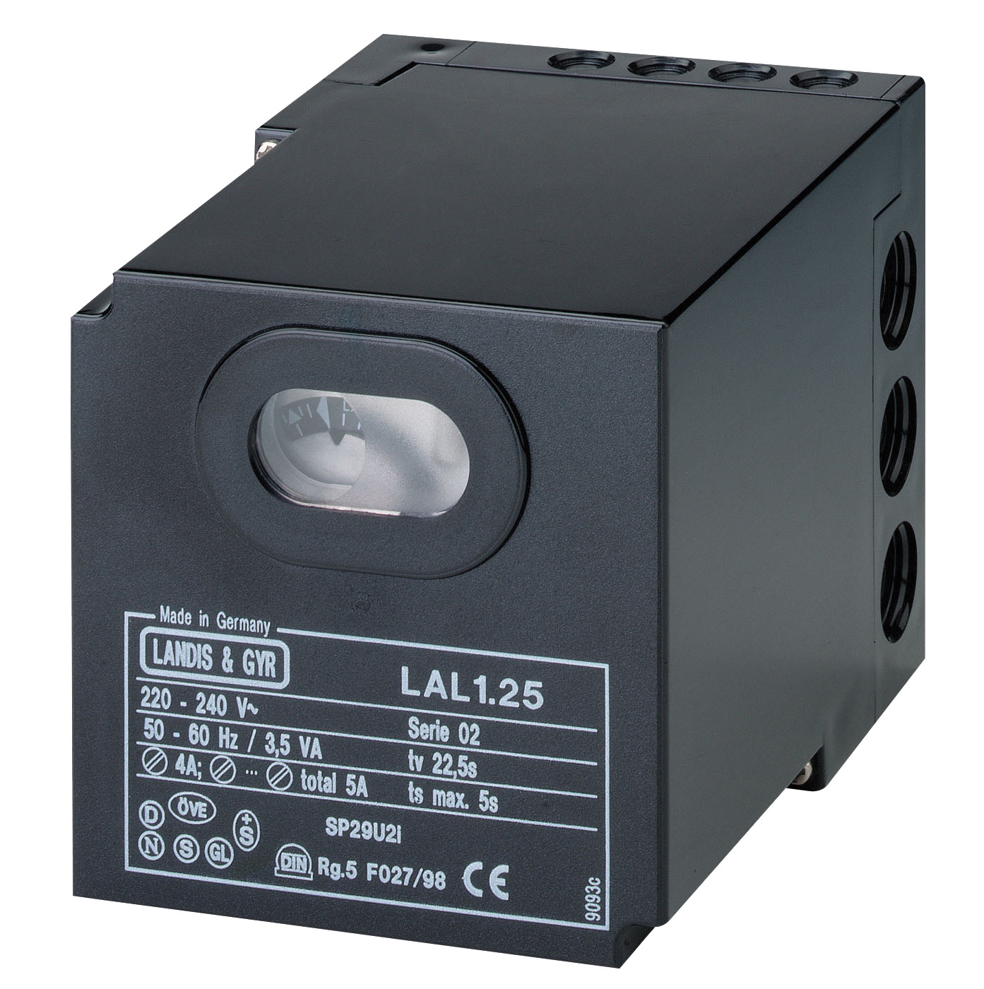
Control Architecture Compatibility: Ensure the selected sensor integrates cleanly with your burner safety relay. The CBM Relay LAL 2.14, for intermittent oil burner service, accepts QRB1, QRC1, or RAR flame sensors—confirming compatibility before procurement prevents costly redesign. Similarly, gas burner controls document their qualified sensor list; always consult technical documentation.
Lifecycle Cost: While photo-resistive cells may have lower initial cost, infrared sensors typically reduce false-alarm service calls, installation labor, and thermal management hardware. Calculate total cost of ownership over a 10–15 year service life.
Regulatory Compliance: Verify that your selected sensor and control combination meet applicable standards (EN 676 for oil burner safety controls, EN 298 for gas burner controls). Compliance data is typically included in technical documentation provided by distributors like 3G Electric.
Closing and Next Steps
Flame detection technology selection is not a commodity decision. The difference between infrared and photo-resistive sensors affects system false-alarm rates, installation complexity, thermal management, and long-term operational cost. Infrared sensors—with spectral selectivity, ambient-light immunity, and thermal robustness—represent the current best practice for most industrial burner applications, particularly oil-fired and biomass systems operating globally. Photo-resistive cells remain viable in specific scenarios where flame color variability dominates the design challenge and environmental conditions permit.
For detailed technical specifications, compatibility matrix guidance, or support in selecting the right flame detection technology for your burner control project, explore 3G Electric's controls and safety product range or contact our technical team. We serve industrial customers worldwide with distribution of leading burner control and flame detection equipment, backed by comprehensive technical documentation and application expertise.