Introduction: System Design Principles for Pumps & Compressors in Southeast Asia
Pumps & Compressors form the backbone of industrial operations across Southeast Asia, from petrochemical plants in Singapore to manufacturing facilities in Thailand and Indonesia. However, simply purchasing individual units doesn't guarantee system reliability—thoughtful system design is critical. With 35+ years of experience as an industrial equipment distributor, 3G Electric has observed that most equipment failures stem not from component defects, but from poor system design, inadequate sizing for ambient conditions, or integration oversights.
This guide addresses the complete system design process: understanding your facility's requirements, selecting complementary components, designing the piping architecture, and commissioning for reliability. Whether you're retrofitting an existing facility or building new capacity, these principles will help you avoid costly downtime and operational inefficiencies.
Section 1: Assessing Facility Requirements and Operating Environment
Understanding Your Load Profile
Before selecting any pump or compressor, you must understand what your facility actually demands. Load profiling involves three key measurements:
Flow Rate Requirements: Determine the volume of fluid (in L/min or cubic meters/hour) your process requires at peak operation. Document both peak and average demands—many facilities operate at full capacity only 40-60% of the time.
Pressure Demands: Identify the minimum and maximum pressure your process requires. High-pressure hydraulic systems may need 160-210 bar continuously, while other applications tolerate 40-80 bar. For Southeast Asian facilities with variable ambient temperatures (20-40°C regularly), pressure stability becomes critical—fluctuations cause component wear.
Duty Cycle: Classify your application:
- Continuous: 24/7 operation (chemical processing, water treatment)
- Intermittent: Regular but not constant operation (manufacturing production runs)
- Standby: Occasional operation with long idle periods (emergency systems, backup capacity)
This classification affects component selection dramatically. Continuous duty requires oversized cooling and more frequent maintenance intervals. Intermittent duty allows smaller, more cost-effective equipment.
Environmental Factors Specific to Southeast Asia
The region's tropical climate presents unique challenges:
Temperature Variation: Ambient temperatures in Bangkok or Jakarta range 22-38°C daily. Fluid viscosity changes significantly over this range—oil that flows freely at 25°C may become sluggish at 35°C, reducing pump efficiency by 8-12%. Design cooling capacity accordingly.
Humidity and Corrosion: Coastal facilities experience salt-air corrosion. Stainless steel components (like those in the Interpump ET1C1612 SX*D20 with PTFE construction) provide superior protection compared to standard carbon steel alternatives.
Power Supply Instability: Many Southeast Asian facilities experience voltage fluctuations and occasional brownouts. Electric motor-driven Pumps & Compressors must include voltage stabilizers and soft-start controllers to prevent component damage.
Space Constraints: Older facilities often lack dedicated equipment rooms. Compact, modular designs like the Interpump E1D1808 L gear pump (5 kg, 8 L/min at 180 bar) suit confined spaces while delivering high pressure.
Section 2: Component Selection and System Architecture
Matching Pump Types to Application Requirements
The three primary pump categories each suit different applications:
Gear Pumps (fixed displacement): Deliver precise flow at high pressure with minimal pulsation. Ideal for:
- Hydraulic power applications requiring 150-210 bar
- Systems where consistent pressure matters more than variable flow
- Compact installations with space limitations
The Interpump E1D1808 L operates at 2800 rpm producing 8 L/min at 180 bar with just 2.72 kW input—excellent for small hydraulic stations in confined spaces.
Centrifugal Pumps (variable displacement with speed): Move large volumes at lower pressures. Best for:
- Water circulation, cooling systems, and flood management
- Applications requiring variable flow without pressure control complexity
- Energy-efficient, low-maintenance continuous operation
- Systems with fluctuating demand (machinery with intermittent cycles)
- Applications requiring energy efficiency—shut-off at zero flow prevents waste
- Complex industrial processes requiring precise pressure regulation
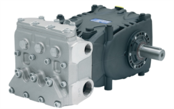
The Pratissoli KF30 (106 L/min at 200 bar, 40 kW) exemplifies modern piston pump technology—Italian-engineered with pressure compensation for Southeast Asian manufacturing applications. For higher-capacity operations, the Pratissoli MW40 (211 L/min at 210 bar, 85 kW) handles double the flow volume while maintaining compact dimensions.
Designing the System Architecture
Your system architecture—the logical arrangement of components—determines reliability and maintainability:
Pump Selection as Primary Component: Choose your pump first based on the most demanding requirement (typically pressure or flow). All downstream components must accommodate this selection.
Pressure Relief System: Install primary relief at the pump outlet (typically 10% above maximum operating pressure) and secondary relief at each load circuit. This prevents overpressure damage during emergency stops.
Filtration Strategy: Hydraulic contamination causes 60-80% of pump failures in Southeast Asian facilities. Specify inlet filters (10 μm absolute) and return filters (3 μm). For critical systems, add off-line kidney-loop filtration operating continuously—this removes contamination introduced during maintenance or normal wear.
Cooling Provisions: Calculate heat load: Power (kW) × 0.8 = Approximate Heat Generation (kW). A 40 kW Pratissoli KF30 generates roughly 32 kW of waste heat. In 30°C ambient conditions, you need coolers sized for 25-30°C above ambient return. Undersized coolers cause viscosity degradation and seal failure within months.
Accumulator Sizing (where applicable): For intermittent-duty systems, accumulators store energy and reduce pump cycling. Size accumulators at 10-15% of system volume for smooth operation and extended component life.
Integration with Existing Infrastructure
Most Southeast Asian facilities retrofit new Pumps & Compressors into existing piping:
- Pipe Sizing: Suction lines should maintain flow velocity below 1.2 m/s (excessive velocity causes cavitation). Discharge lines can tolerate 2-4 m/s. Oversized piping reduces pressure drop and heat generation.
- Vibration Isolation: Install the pump on elastomeric mounts to prevent vibration transmission to the facility structure. This is critical in multi-story facilities or food/pharmaceutical plants where vibration causes product contamination.
- Noise Attenuation: High-pressure Pumps & Compressors generate 75-85 dB. In residential-adjacent facilities, add acoustic enclosures around pump stations.
- Maintenance Access: Ensure 1.5-meter clearance around all pump components for seal replacement, hose disconnection, and troubleshooting.
Section 3: System Commissioning and Performance Validation
Pre-Startup Verification
Before introducing pressurized fluid:
1. Verify all connections match design specifications. High-pressure mismatches (connecting 200 bar components to 160 bar manifolds) cause catastrophic failure.
2. Confirm fluid compatibility—ISO 32 hydraulic oil may be incompatible with certain seal materials. Test with small quantities before full commissioning.
3. Check motor rotation direction—reversing the pump inlet and outlet causes instant cavitation damage. Mark rotation direction clearly.
4. Flush the system before the pump operates—even "clean" pipes contain weld debris and machining residue that destroy pump internals.
Operational Startup Protocol
Phase 1 - No-Load Running (15-30 minutes):
- Start the prime mover (electric motor or engine) at low speed
- Open pump discharge isolation valve slowly
- Allow fluid circulation at minimal pressure (below 20 bar) to bleed air and warm the fluid
- Monitor for unusual noise, vibration, or temperature rise
- Gradually increase system pressure toward operating setpoint
- Observe pressure gauge readings—pressure should stabilize within ±5 bar of setpoint
- Monitor outlet temperature—should not exceed 50°C during this phase
- Check all hose connections for weeping (microscopic leaks indicate assembly issues)
- Run at full operating pressure for 2-4 hours
- Record baseline measurements: inlet temperature, outlet temperature, pump inlet vacuum (should be below 0.3 bar), outlet pressure, and amperage (for electric motors)
- Document all readings in your commissioning log—these become references for future troubleshooting
Performance Validation Against Design Specifications
After commissioning, validate performance:
| Parameter | Expected Range | Acceptable Variance | Investigation Threshold |
|-----------|---|---|---|
| Flow Rate | Design ±5% | ±8% | >±10% indicates internal leakage |
| Discharge Pressure | Setpoint ±2 bar | ±5 bar | >±8 bar suggests relief valve drift |
| Inlet Vacuum | 0.1-0.2 bar | 0.3 bar max | >0.4 bar indicates suction-line restriction |
| Outlet Temperature | Ambient +15-25°C | +30°C max | >+35°C above ambient requires cooler upgrade |
| Motor Amperage | Design ±10% | ±15% | >±20% indicates viscosity or internal resistance change |
For example, if your Pratissoli MW40 (211 L/min at 210 bar) produces only 190 L/min at full pressure after six months of operation, internal leakage has increased—schedule seal inspection within 30 days before catastrophic failure occurs.
Section 4: Ongoing Monitoring and System Optimization
Establishing a Baseline Monitoring Program
The most cost-effective maintenance happens before problems develop. Establish these monthly checks:
Visual Inspection:
- Check hose condition for cracks, abrasion, or external contamination
- Verify all connections remain tight (vibration loosens fittings over months)
- Inspect seals for leakage—small weeps become major leaks quickly in humid environments
- Record outlet temperature at the same operating conditions monthly
- Trending a 2-3°C monthly temperature rise indicates cooling capacity erosion or internal component wear
- Plot these on simple spreadsheet charts—trends matter more than individual readings
- Send fluid samples quarterly to a laboratory for particle count and viscosity analysis
- Results guide filter maintenance frequency—if particle counts exceed ISO 4406 code 18/16/13 in hydraulic systems, increase filtration frequency or upgrade filter media
Optimization Opportunities
After 6-12 months of operation, review system performance:
Energy Efficiency Audit: If outlet temperature exceeds design by >5°C, calculate annual energy cost. Upgrading cooler capacity may have 18-24 month payback through reduced electricity consumption.
Pressure Optimization: If your process uses 210 bar but maximum demand is only 150 bar, reducing system pressure to 160 bar decreases component wear by 30-40% and cooling load by 25%, with no operational impact.
Flow Balancing: Uneven flow distribution between parallel circuits causes some components to work excessively while others remain underutilized. Flow meters ($300-600) reveal imbalances; proportional valves ($2,000-4,000) correct them, extending equipment life significantly.
Seasonal Adjustments for Southeast Asia
Summer (March-May) and monsoon (September-November) periods stress Pumps & Compressors differently:
- Pre-Summer: Increase cooler target setpoint 2-3°C and verify backup cooling capacity. Power outages are more frequent; ensure adequate thermal mass in the system.
- Pre-Monsoon: Inspect all seals and hose connections—humidity causes seal degradation. Stock replacement hoses and seal kits locally to minimize downtime during supply chain disruptions.
Conclusion
Designing effective Pumps & Compressors systems requires balancing technical specifications, environmental realities, and maintenance practicality. With 35+ years of industrial distribution experience, 3G Electric has supplied facilities across Southeast Asia with components matching these exact principles.
Whether you're implementing a compact 8 L/min Interpump system in a confined Bangkok facility or scaling to large Pratissoli 211 L/min installations for Thai manufacturing, the design methodology remains consistent: understand your requirements deeply, select components that work together harmoniously, commission thoroughly, and monitor continuously.
Start your next project by documenting load requirements, ambient conditions, and space constraints. These inputs define everything downstream. 3G Electric's technical team can validate your design approach and recommend specific components from our extensive inventory of Italian-engineered pumps and global industrial equipment.