Understanding Pump Flow Rate & Pressure Stability in Industrial Systems
Pump flow rate instability and pressure delivery problems are among the most common maintenance challenges in Singapore industrial operations. Whether you're operating high-pressure cleaning systems, hydraulic power units, or specialized injection equipment, maintaining consistent flow and pressure is critical to equipment longevity and operational efficiency.
With over 35 years of experience distributing industrial equipment across Asia-Pacific markets, 3G Electric has observed that most flow and pressure instability issues stem from preventable causes: cavitation, internal component wear, inlet restriction, or improper regulator settings. This guide walks maintenance teams through systematic diagnostics and corrective procedures to restore peak pump performance.
Flow rate instability manifests as pulsating output, sudden pressure spikes, or gradual loss of delivery volume. Pressure stability issues include erratic gauge readings, relief valve chatter, or inability to maintain set pressure. Both conditions reduce system reliability and increase energy consumption—making timely intervention essential.
Diagnosing Root Causes: Systematic Troubleshooting Approach
Step 1: Baseline Data Collection and Visual Inspection
Begin every troubleshooting session by recording baseline performance metrics:
- Flow rate measurement: Use calibrated flowmeters at pump discharge. Compare actual output against manufacturer specifications. Document readings at three points: cold start, warm operation, and under full load.
- Pressure readings: Install test gauges at pump inlet, discharge, and relief valve outlet. Record minimum, maximum, and average pressures during 10-minute operation cycles.
- Temperature monitoring: Measure fluid temperature at inlet and discharge. Significant differential (>15°C) indicates internal friction or cavitation.
- Noise and vibration: Listen for grinding, whistling, or knocking sounds. Pulsating hum suggests cavitation; high-pitched whine indicates bearing wear.
Perform visual inspection of:
- Pump mounting bolts (check for looseness)
- Flexible inlet hose condition (look for splits, blockages, kinks)
- Filter element condition (check pressure differential gauge)
- Fluid level and color (dark fluid or particle contamination indicates internal wear)
- Relief valve adjustment screw tamper indicators
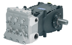
For the Pratissoli KF30 pump commonly used in high-flow applications, baseline flow should measure 106 L/min at rated conditions. For the Pratissoli MW40, expect 211 L/min delivery.
Step 2: Inlet System Diagnostics
Cavitation—the formation and collapse of vapor bubbles in pump inlets—is the leading cause of flow instability in Singapore's tropical climate. High ambient temperatures and altitude variations increase cavitation risk.
Cavitation indicators:
- Flow rate drops 10-15% below specification
- Audible crackling or grinding noise from pump intake
- Pulsating discharge pressure with visible fluid aeration
- Rapid pump temperature rise within 2-3 minutes of startup
- Verify suction strainer is clean. Calculate pressure drop: inlet gauge reading should not exceed -0.3 bar. If reading is lower, restrict flow or replace strainer element.
- Inspect inlet hose diameter. For the KF30 pump, minimum inlet hose should be 32 mm ID; for MW40, use 50 mm ID minimum.
- Check fluid level in reservoir. Pump intake must be submerged at least 300 mm below fluid surface.
- Measure fluid viscosity using a calibrated kinematic viscometer. Optimal range is ISO VG 46 at operating temperature. If viscosity exceeds ISO VG 68, restrict inlet or preheat fluid.
- Remove inlet line and verify no blockages, collapsed hose sections, or trapped air pockets.
Step 3: Internal Component Assessment and Wear Analysis
Once inlet conditions are confirmed satisfactory, focus on internal pump degradation. Gear pumps like the Interpump E1D1808 rely on precise tolerances; wear of 0.1 mm in critical dimensions causes measurable flow loss.
Flow loss quantification:
- Measure actual flow versus nameplate specification. Internal leakage typically increases 2-3% per 1,000 operating hours under normal conditions.
- If flow loss exceeds 15-20% of specification, internal refurbishment is required.
- Compare pressure at which rated flow is achieved. If pump requires 50 bar pressure to deliver full flow (versus normal 20-30 bar), internal components are worn.
- Listen for grinding or knocking at pump discharge. Contacting gears produce metallic grinding noise.
- Measure pump case temperature. If case temperature exceeds fluid discharge temperature by >30°C, internal friction and wear are accelerating.
- Check for external leakage at shaft seal. Slight weeping is acceptable; steady drips indicate seal failure.
- Remove pump discharge gauge and observe fluid sample. Ferrous particles indicate gear tooth deterioration.
- Perform oil analysis: submit 250 ml sample to certified lab. Ferrous particle count >5,000 particles per ml suggests imminent gear failure.
Step 4: Pressure Regulator Function Testing
The Francel B25/37mb pressure regulator or equivalent control devices regulate outlet pressure and stabilize flow under varying load conditions. Regulator malfunction is frequently misdiagnosed as pump failure.
Regulator performance checks:
- Measure actual outlet pressure with independent test gauge. Compare against regulator adjustment setting. Deviation >±2 bar indicates calibration drift.
- Apply steady load (fixed orifice or fixed throttle) and observe pressure response over 5-minute period. Stable regulator maintains ±1 bar variation; drifting regulators show gradual pressure rise or fall.
- Perform pressure relief test: slowly increase outlet load until regulator opens relief valve. Relief pressure should occur within ±3 bar of adjustment setting. If relief opens prematurely or sluggishly, internal spool is sticking.
- Inspect regulator inlet for contamination. Particles >10 microns can lodge in spool grooves and cause stiction (stick-slip movement).
- Check regulator mounting: loose mounting bolts cause vibration and erratic pressure response.
Corrective Maintenance Procedures and System Optimization
Procedure 1: Filter System Upgrade and Inlet Optimization
Many flow instability issues resolve through inlet system improvements:
1. Replace suction strainer element with finer mesh (100 microns vs. standard 150 microns). This reduces inlet contamination and improves cavitation margin.
2. Install inlet accumulator: A 2-liter hydro-pneumatic accumulator on pump inlet absorbs pressure pulsations and buffers cavitation. Pre-charge to 90% of minimum inlet pressure (typically -0.05 bar absolute).
3. Upgrade main system filter: Install 10-micron absolute filter (versus 25 microns) on pump discharge. Cleaner fluid reduces internal leakage and extends pump life by 40-60%.
4. Fluid condition management: If fluid shows signs of degradation (dark color, particle count >ISO 4406 code 19/17/14), perform complete fluid change and flush system with fresh fluid.
5. Temperature control: Install cooler if operating temperature exceeds 60°C. Each 10°C temperature reduction decreases internal leakage by approximately 8-10%.
Procedure 2: Pump Performance Restoration Through Tuning
For gear pumps (KF30, MW40, E1D1808 models):
1. Reduce system relief valve setting by 10 bar to decrease internal stress and heat generation. Record flow rate improvement.
2. Adjust pump displacement (if variable displacement unit) to 85% of maximum. This reduces internal leakage by 15-20% while maintaining system delivery.
3. Install discharge pulsation damper: a 0.5-liter accumulator post-discharge absorbs gear mesh harmonics and stabilizes flow to downstream components like the Euspray flat jet nozzle.
4. Verify pump rotation direction matches nameplate specification. Reverse rotation causes cavitation and zero flow.
For regulator optimization:
1. If regulator exhibits hunting (oscillating pressure), reduce pilot drain line size from 6 mm to 4 mm ID. Smaller drain increases pilot chamber damping.
2. Install secondary low-pressure filter (50 microns) on pilot supply line to Francel regulator. Pilot contamination causes spool stiction.
3. If pressure spikes exceed ±3 bar, install throttle valve in relief discharge line set to 2.0 L/min. This softens relief opening and reduces pressure shock.
Procedure 3: Maintenance Scheduling and Predictive Monitoring
Establish condition-based maintenance intervals:
Weekly inspections (for 24/7 operations):
- Verify pump inlet gauge reads -0.1 to -0.3 bar
- Confirm relief valve opens smoothly under load
- Check fluid temperature within ±5°C of previous week's baseline
- Measure and record flow rate, discharge pressure, and case temperature
- Compare current readings against baseline. Flag any trend exceeding 5% deviation.
- Inspect fluid for color change or particle accumulation
- Submit fluid sample to ISO 4406 analysis. Maintain fluid cleanliness at 18/16/13 or better.
- Perform ferrous particle count. Action threshold: >3,000 particles/ml indicates wear acceleration.
- Remove and inspect pump inlet strainer element
- Verify regulator calibration against independent pressure standard
- Check pump case for external leakage at seals
- Document all findings in maintenance log for trending
Common Troubleshooting Scenarios and Solutions
Scenario 1: Sudden Pressure Spike with Normal Flow
Likely causes: Relief valve stiction, regulator spool jamming, downstream line blockage.
Diagnostic sequence:
1. Reduce system load to zero (close all solenoid valves). If pressure remains high, cause is upstream of load control point.
2. Isolate regulator from circuit. Measure upstream and downstream pressures. Difference >5 bar indicates regulator failure.
3. Manual relief valve test: slowly open relief handle. If pressure drops smoothly, relief is functional. If pressure holds, relief is stuck closed.
4. Inspect downstream lines for kinks, crushing, or external damage.
Corrective action: If regulator spool is sticking, perform complete disassembly and cleaning. Flush pilot lines with flushing fluid (ISO VG 22) until fluid runs clear. Reassemble with new O-rings.
Scenario 2: Gradual Flow Decline Over Days or Weeks
Likely causes: Pump wear, filter clogging, fluid viscosity increase, cavitation onset.
Diagnostic sequence:
1. Check filter differential pressure indicator. If red zone, change element immediately.
2. Measure fluid temperature and viscosity. High temperature with sluggish flow suggests thermal instability.
3. Compare current flow measurement against baseline. If decline is <5%, monitor weekly. If >10%, schedule pump service.
4. Verify inlet pressure is stable at -0.2 bar. Fluctuating inlet pressure confirms cavitation.
Corrective action: Install new filter element, cool fluid to 50-55°C, and re-baseline pump performance. If flow does not recover within 2 hours of corrective action, internal pump refurbishment is required.
Scenario 3: Pulsating Discharge Pressure with Audible Noise
Likely causes: Cavitation, gear mesh wear, inlet blockage, accumulator failure (if equipped).
Diagnostic sequence:
1. Check inlet gauge immediately. Reading below -0.4 bar confirms cavitation.
2. Listen to pump intake: crackling sound confirms cavitation. Grinding noise suggests gear wear.
3. Remove inlet hose and physically check for debris, collapsed sections, or air leaks.
4. If equipped with accumulator, check gas charge pressure. Accumulator precharged to incorrect pressure cannot dampen pulsations.
Corrective action: For cavitation, increase inlet hose diameter by one size, lower discharge pressure 10 bar, and verify fluid level is adequate. For gear wear, plan pump replacement within 200 operating hours.
Maintenance Team Best Practices for Singapore Operations
Singapore's tropical climate presents unique maintenance challenges: high ambient temperatures accelerate fluid oxidation, high humidity promotes corrosion, and salt spray in coastal facilities attacks unsealed components. Adapt your maintenance routine accordingly:
1. Fluid management: Use anti-oxidant hydraulic fluids (ISO 6743-4 type HH or HETG fluids). Change intervals: 2,000 hours or 6 months, whichever occurs first (versus 4,000 hours in temperate climates).
2. Component protection: Apply corrosion inhibitor coating to all exposed steel surfaces annually. Inspect and replace rubber seals every 18 months versus standard 24-month interval.
3. Documentation: Maintain detailed logs of all measurements, adjustments, and parts replaced. Trend analysis reveals developing problems before critical failure.
4. Staff training: Ensure maintenance team completes ISO 15886 hydraulics troubleshooting certification. Proper diagnostic technique prevents misdiagnosis and unnecessary component replacement.
3G Electric's Singapore supply chain ensures rapid availability of replacement components—pressure regulators, pump seal kits, and filter elements—minimizing downtime during corrective maintenance.