Understanding Controls & Safety Interlock Architecture
Controls & Safety in industrial burner systems extends far beyond simple on-off switches. Modern plant operations demand sophisticated electrical interlock systems that prevent dangerous fuel-air-ignition sequences through layered protection mechanisms. An electrical interlock is a hardwired or logic-based safety device that enforces mandatory operational sequences—ensuring that certain conditions must be met before subsequent steps can occur.
The fundamental principle behind Controls & Safety interlocks is fail-to-safe design: if any component fails, the system defaults to a non-hazardous state. This contrasts with fail-to-operation designs, which are unsuitable for safety-critical applications. With 35+ years of experience distributing industrial burner equipment, 3G Electric has observed that plant managers who understand interlock architecture achieve dramatically better uptime rates and incident prevention records.
Electrical interlocks prevent three critical failure modes in burner systems:
- Uncontrolled fuel delivery before ignition is confirmed
- Ignition attempts with inadequate air supply or fuel pressure
- Continued combustion when safety parameters drift outside acceptable ranges
The electrical pathway must be designed such that a single failure—whether sensor malfunction, wiring fault, or component degradation—cannot result in a hazardous condition. This typically requires dual-channel sensing, redundant shutdown paths, and periodic proof-testing of the safety function itself.
Sequencing Logic and Component Selection for Interlock Implementation
Proper sequencing logic defines the mandatory operational sequence that your burner system must follow. The typical fail-safe burner start sequence includes:
1. Pre-purge phase: Fan operates for 30-60 seconds to clear the furnace of residual fuel vapors, with interlock verification that fan is running before allowing fuel valve actuation
2. Fuel valve opening: Solenoid valve energizes only after purge timer completion and proof of air flow
3. Ignition engagement: Spark or hot surface igniter activates only after fuel is flowing and air supply is confirmed
4. Flame establishment: System monitors flame signal continuously; shutdown occurs within 4 seconds if flame is not detected
5. Safe shutdown sequence: Fuel valve de-energizes immediately on demand, ignition ceases, and fan continues for post-purge cooling
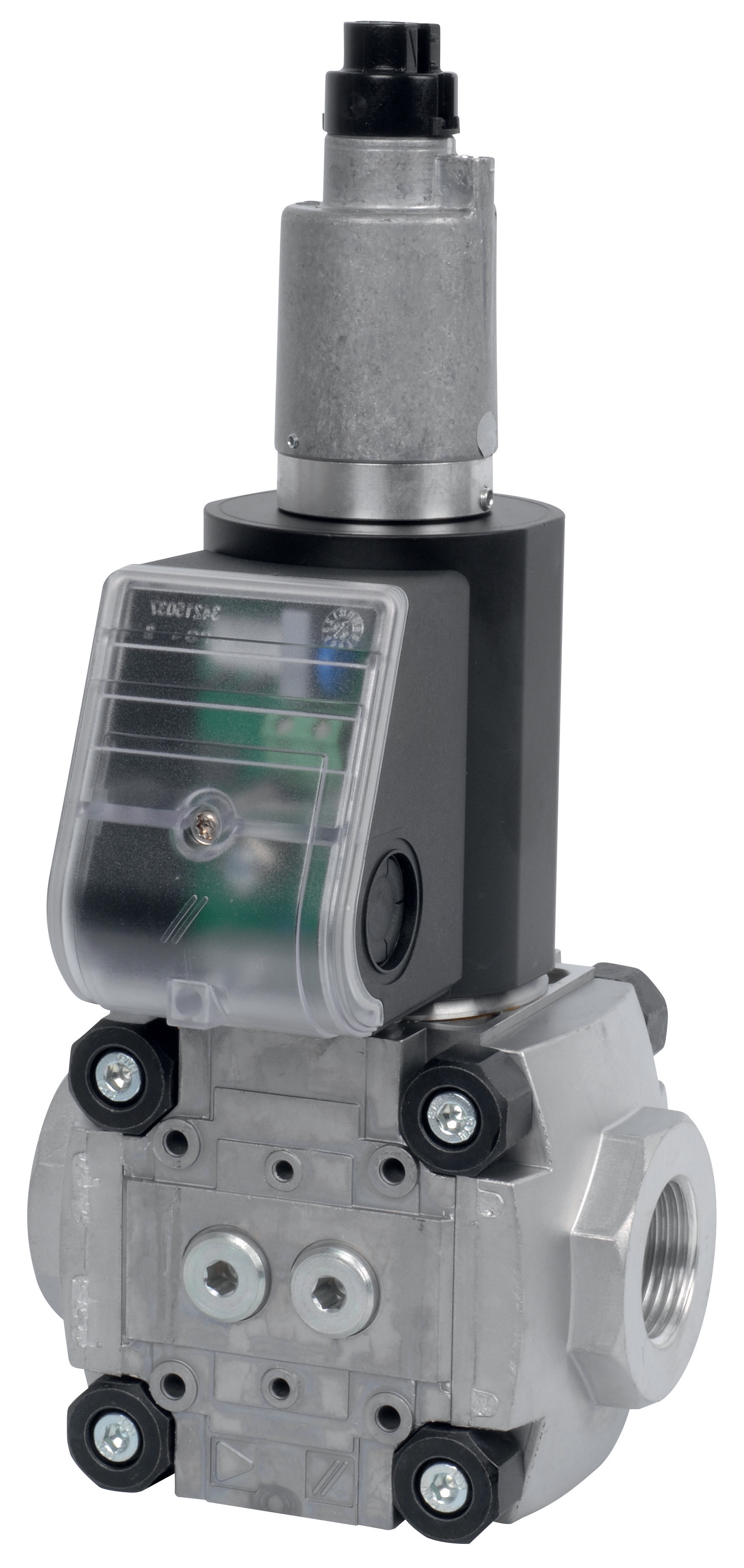
Component selection directly impacts interlock reliability. The solenoid valves you specify must match both the gas type and response-time requirements of your sequence. For applications requiring rapid fuel shut-off (less than 100ms), the CBM Fast gas solenoid valve VAS 110R/NW provides the speed necessary to interrupt combustion before temperature or pressure excursions damage equipment.
Conversely, slower ramp rates prevent pressure shock and flame disturbance in gentler applications. The CBM Slow gas solenoid VAS 125R/LW and CBM Slow gas gas solenoid valve VAS 340R/LW control gas feed rates with precision, minimizing pressure transients while maintaining sequence integrity. For larger flow applications demanding controlled gas delivery, the CBM Fast gas EV VAS 365R/NW combines high flow capacity with rapid response characteristics.
Relay selection forms the electrical backbone of interlock logic. The CBM Relay DMG 970-N MOD.03 integrates multiple safety functions—flame monitoring, pressure sensing, and timer logic—into a single modular package. This consolidation reduces wiring complexity, improves maintainability, and provides certification-ready safety architecture. Modern safety relays implement self-checking diagnostics that continuously verify proper operation of internal contacts and coils, detecting failures before they compromise safety.
Plant managers should specify components with clearly documented response times and failure modes. A solenoid valve with 150ms closing time is unusable in an interlock designed to shut off fuel in 100ms—this mismatch will eventually cause unsafe operation during demand scenarios. Always cross-reference the full sequence timing requirements against component datasheets before finalizing designs.
Practical Commissioning and Testing Protocols
Theoretically sound interlocks fail in practice when commissioning is incomplete or inadequate. Each interlock function must be proven during startup before the burner operates under full load.
Pre-energization verification involves confirming proper wiring continuity, relay coil resistance, and solenoid valve continuity before applying power. This prevents control transformer damage and identifies basic assembly errors. Megger testing of all control circuits to ground (minimum 5 MΩ) confirms isolation and absence of moisture contamination.
Manual sequence testing with the fuel train isolated verifies that each step logically prevents the next unauthorized step. Disable the flame sensor and attempt fuel valve energization—the valve should not open. Verify that purge timers enforce their duration before fuel valve circuits become available. Test pressure switches by simulating low-air or low-fuel pressure conditions; the burner must shut down without manual intervention.
Flame failure testing is critical and often overlooked. With fuel flowing and burner firing normally, manually interrupt the flame (cover the burner opening or disable ignition) and measure how quickly the system shuts down fuel delivery. Target is typically under 4 seconds. A slower response indicates failing flame detection circuitry or relay timing drift.
Load-step testing under actual operating conditions reveals interlock weaknesses that laboratory procedures miss. Increase burner load in small increments while monitoring all sensor signals and solenoid valve states. Watch for unexpected valve dithering (rapid opening-closing cycles) which indicates tuning problems in the control logic. Verify that pressure and temperature remain within design limits throughout the load range.
Document all test results and establish baseline performance metrics. These become the foundation for preventive maintenance intervals. If flame shutdown time increases from 2 seconds to 3.5 seconds over six months, this signals degrading flame detection performance requiring imminent replacement before failure occurs.
Maintenance and Proof-Testing Strategy for Safety Integrity
Safety interlocks degrade predictably through normal operation. Solenoid coils develop higher resistance, relay contacts accumulate carbon residue, and sensor optics become fouled. Without systematic maintenance, an interlock with 99% reliability at commissioning may degrade to 85% reliability after 12 months of service.
Implement a quarterly proof-test program where each safety function is manually tested to verify proper operation. During proof-testing, technicians physically interrupt each protective function (close manual block valves, cover flame sensors, simulate pressure faults) and confirm the burner shuts down safely. Document results; trending data (increasing shutdown times, reluctant solenoid actuation) predicts component failure 2-4 weeks in advance of catastrophic failure.
Solenoid valve maintenance focuses on filter element changes (every 6 months minimum in dusty environments) and coil inspection for moisture contamination. The VAS 110R/NW and VAS 365R/NW fast-acting valves are particularly sensitive to filter bypass, as particulate lodging in the poppet prevents tight sealing and causes slow shutdowns. The slower valves—VAS 125R/LW and VAS 340R/LW—tolerate slightly higher particulate loads but still require regular filtration monitoring.
Relay maintenance on units like the DMG 970-N MOD.03 involves contact inspection and coil resistance measurement. Compare resistance values against manufacturer baseline specifications; deviations exceeding 5% indicate internal corrosion requiring replacement. Many modern relays include self-diagnostic LEDs and programming ports; use these to verify internal logic integrity quarterly.
Establish a predictive maintenance schedule based on equipment operating hours and failure history. Most industrial burner interlocks benefit from component replacement on a 3-5 year cycle, with more aggressive schedules (1-2 years) in harsh chemical plant environments or where flame failures are frequent indicators of sensor fouling.
Plant managers implementing systematic Controls & Safety maintenance programs report 40-60% reductions in unexpected burner shutdowns compared to reactive maintenance approaches. This translates directly to improved process uptime and reduced emergency service costs.