Understanding Oil Burner Atomization in Tropical Environments
Oil burner atomization—the process of breaking fuel into fine mist for combustion—is critical to efficient Burners & Combustion performance. In Southeast Asia's humid climate, moisture contamination, carbon buildup, and nozzle degradation occur faster than in temperate zones. With over 35 years of experience distributing industrial heating equipment across Asia-Pacific, 3G Electric has observed that atomization failures account for 40% of unplanned burner shutdowns in the region.
Atomization depends on three factors: fuel pressure, nozzle condition, and viscosity management. When any fails, the spray pattern breaks down, combustion becomes inefficient, and your control systems may trigger safety interlocks. The Siemens safety relay units like the Siemens LFL 1.622 detect flame instability caused by poor atomization and shut the burner down—a protective response that stops production until you resolve the root cause.
Diagnosing Fuel Pressure and Nozzle Problems
Measuring Atomization Pressure
Start with fuel pressure measurement at the nozzle inlet. Oil burners require 8–10 bar (for light oil) or 10–15 bar (for heavy oil, depending on viscosity). Use a calibrated pressure gauge with a tee fitting installed upstream of the nozzle.
- Low pressure (below specification): Check the fuel pump outlet pressure first. If the pump output is correct but pressure drops at the nozzle, you have a blockage in the fuel line, a leaking high-pressure hose, or a dirty strainer. Clean or replace the fuel filter and inspect all fittings for seepage.
- Excessive pressure (above 15 bar): The pump may be oversized, or the pressure relief valve (PRV) is stuck closed. Manual override of the PRV should release pressure; if not, replace the valve. High pressure forces atomization but can damage the nozzle tip and create overly fine particles that don't combust efficiently.
- Fluctuating pressure: Cavitation in the fuel line or a failing pump indicates air ingress or internal pump wear. Bleed air from the fuel system and verify the tank's fuel level is above the pump intake.
Nozzles fail in predictable ways in tropical climates:
- Carbon buildup: Black, crusty deposits on the nozzle tip restrict fuel flow and distort the spray pattern. Remove the nozzle (mark its orientation first), soak it in solvent for 2–4 hours, and use a soft brush. Do not use wire brushes—they enlarge the orifice and change the spray angle. If soaking doesn't remove carbon, replace the nozzle.
- Erosion or chipping: Inspect the tip under magnification (10×). Sand particles in fuel can erode the orifice. If the tip is chipped or has a visible groove, replacement is necessary; repair is not reliable.
- Wet nozzle (fuel seeping from the tip at rest): The nozzle valve seat is worn or contaminated. Replace the nozzle. If seepage continues after replacement, the pump discharge check valve is faulty.
In Southeast Asia, ambient temperatures can exceed 35°C, affecting fuel viscosity. Heavy oil (HFO or marine diesel) thickens in cooler months and thins in heat.
- Measure viscosity using a Saybolt viscosity cup or request a fuel analysis from your supplier.
- If viscosity exceeds 50 cSt (centistokes), preheat the fuel to 40–50°C using an electric heater or steam jacket on the fuel tank.
- Preheating reduces viscosity, lowers atomization pressure requirements, and prevents pump cavitation.
- Install a thermometer and pressure gauge together; record both readings during startup to establish baseline performance.
Diagnosing Control System Interference with Atomization
Pressure Switch Hysteresis
The Kromschroder DG 50U/6 pressure switch monitors fuel pressure and signals the burner control relay to start ignition. If the switch setting is too high or the deadband (hysteresis) too wide, the burner may start and stop repeatedly during modulation.
- Measure the pressure at which the switch closes (make contact) and opens (break contact).
- For light oil burners, the differential should be 0.5–1 bar; for heavy oil, 1–1.5 bar.
- If the switch is stuck or has no hysteresis, fuel pressure fluctuations cause nuisance shutdowns. Replace the pressure switch.
The Kromschroder BCU 570WC1F1U0K1-E relay coordinates fuel valve, ignition, and combustion air fan timing. If the relay's ignition delay is too short or too long, the fuel nozzle may not achieve stable atomization before the flame monitoring system (UV or ionization detector) expects to see a flame.
- Verify the relay's ignition delay setting (usually 3–5 seconds for oil burners).
- If the burner flickers or shuts down after ignition, extend the delay by 1–2 seconds to allow atomization to stabilize.
- Check that the flame monitoring system (e.g., the ionization electrode in the combustion chamber) is clean and properly gapped (typically 3–4 mm).
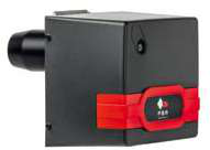
The FBR KN 1300/M TL EL dual-fuel burner modulates combustion air and fuel together. If the damper actuator controlling air supply is sluggish or miscalibrated, the air-fuel ratio becomes too lean, causing flame instability and smoke.
- At ignition, the damper should be fully open (maximum air).
- During operation, the damper should modulate proportionally with fuel valve opening.
- Test damper response by manually adjusting the fuel valve and observing the air damper position. If the damper lags by more than 5 seconds, the actuator needs cleaning or replacement.
Practical Troubleshooting Workflow for Atomization Issues
Step 1: Initial Observations (5 minutes)
- Observe the flame color: bright yellow or orange with sooty smoke indicates incomplete combustion (too much fuel, not enough air, or poor atomization). Clean blue flame means combustion is efficient.
- Listen for burner noise: a dull roar suggests a narrow spray cone due to nozzle wear; a sharp hiss indicates high pressure and fine atomization, which may be too efficient.
- Check the burner for smoke emission during startup and shutdown.
- Measure fuel tank level; low level increases pump cavitation risk.
- Feel the fuel line near the nozzle—it should be warm but not hot. If cold, preheating is not operating or is undersize.
- Listen at the fuel filter for gurgling (air) or silence (blockage).
- Record fuel pressure with the burner running at 100% load and at 50% modulation (if the burner supports modulation).
- Stop the burner and allow 15 minutes for the system to cool.
- Remove the nozzle, inspect for carbon and erosion, and measure the orifice diameter with a calibrated hole gauge (compare to the manufacturer's specification).
- While the nozzle is removed, activate the fuel pump and check for fuel seepage from the discharge line (nozzle removed). If fuel seeps, the pump check valve is worn.
- Measure the pressure switch opening and closing points with a handheld pressure gauge connected to a tee fitting.
- Verify the ignition sequence: fuel valve should open after the air damper and combustion fan are running.
- Check the flame detector (ionization electrode or UV cell) for dirt or misalignment.
- Clean the electrode with a soft dry cloth; do not use solvents that leave residue.
- Start the burner and observe the ignition sequence from air damper opening to flame establishment.
- Record fuel pressure, combustion air temperature (if available), and flue gas temperature at full load.
- Shut down the burner and observe the nozzle tip with a flashlight to confirm fuel seepage stops within 10 seconds (normal).
- Document all readings in your service log for trend analysis.
Regional Considerations for Southeast Asian HVAC Contractors
Humidity and Moisture Contamination
Tropical humidity means fuel tanks accumulate water at the bottom. Quarterly fuel analysis and water removal via settling tanks or centrifuges prevents nozzle corrosion and emulsions that block atomization.
Component Availability and Lead Times
3G Electric's 35+ years of distribution experience across Southeast Asia means we maintain stock of common replacement items: nozzles, pressure switches, and control relays. Order spare parts before the rainy season when supply chains are strained. The Kromschroder DG 50U/6 pressure switch and BCU 570WC1F1U0K1-E relay are stocked regionally and typically available within 3–5 business days.
Preventive Maintenance Schedule
- Monthly: Inspect fuel tank level and water separation tank.
- Quarterly: Fuel analysis (viscosity, water content, sediment).
- Semi-annually: Nozzle inspection and cleaning; pressure switch calibration.
- Annually: Complete burner service, including control relay testing and flame detector cleaning.
Following this schedule reduces unplanned shutdowns by 60% in high-utilization industrial heating applications common in the region.